Rotary-driven electronic fitting welding device

A technology of rotary drive and welding device, applied in auxiliary devices, welding equipment, auxiliary welding equipment, etc., can solve the problems of low welding efficiency, inability to form an automated production line, unsafe operation methods, etc., and achieve high welding efficiency and high degree of automation. , easy to use effect

Inactive Publication Date: 2019-02-15
东台市高科技术创业园有限公司
6 Cites 0 Cited by

AI-Extracted Technical Summary

Problems solved by technology

[0002] The existing welding of electronic accessories is generally manual welding after manual clamping, but the welding ef...

Method used

The present invention can drive telescoping device to rotate by drive mechanism, easy to use; The present invention can rotate on positioning block by telescopi...

Abstract

The invention discloses a rotary-driven electronic fitting welding device. The rotary-driven electronic fitting welding device comprises a base, an extension device, a positioning block, a welding rodand a driving mechanism. The driving mechanism can drive the extension device to rotate to achieve convenience to use; the extension device is rotated on the positioning block; and then, electronic fittings in multiple accommodating tanks of the base are welded through the welding rod, so that the welding is efficient, and the automation degree is high.

Application Domain

Technology Topic

Image

  • Rotary-driven electronic fitting welding device

Examples

  • Experimental program(1)

Example Embodiment

[0014] The content of the present invention will be further described in detail below in conjunction with the accompanying drawings.
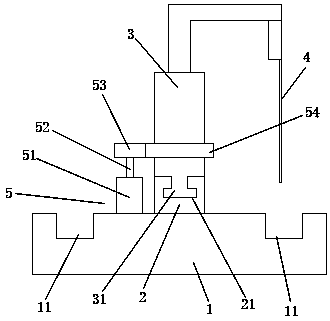
[0015] Such as figure 1 As shown, a rotary drive type electronic accessory welding device includes a base 1, a telescopic device 3, a positioning block 2, a welding rod 4, and a driving mechanism 5; the base 1 is evenly provided with accommodating grooves 11 around the circumference; The upper end of the base 1 is equipped with a positioning block 2 in the middle; the upper end of the positioning block 2 is rotated to install a telescopic device 3; the upper side of the telescopic device 3 is installed with a welding rod 4; the welding rod 4 is rotated and telescopic in the base 1 Just above the slot 11. The driving mechanism 5 includes a driving motor 51, a rotating shaft 52, a driving gear 53, and a driven gear ring 54; the driving motor 51 is installed on the base 1; the upper end of the driving motor 51 rotates to drive the rotating shaft 52; The upper end of the rotating shaft 52 is equipped with a driving gear 53; the driven gear ring 54 is installed on the outside of the telescopic device 3; the driving gear 53 is engaged and connected to the outside of the driven gear ring 54.
[0016] Such as figure 1 As shown, further, the telescopic device 3 is a telescopic cylinder or a telescopic oil cylinder. Further, the bottom of the telescopic device 3 is provided with a rotating clamping tooth 31; the upper end of the positioning block 2 is provided with a rotating clamping groove 21; the telescopic device 3 is rotatably clamped by the rotating clamping tooth 31 The positioning block 2 is in the rotating clamping slot 21. Further, the positioning block 2 is made of friction-resistant material. Further, a wear-resistant layer is provided in the rotary clamping groove of the positioning block 2. Further, the wear-resistant layer is a polytetrafluoroethylene coating.
[0017] The present invention can drive the telescopic device to rotate through the drive mechanism, which is convenient to use; the present invention can rotate the positioning block through the telescopic device, and then weld the electronic accessories in the accommodating slots of the multiple bases through the welding rod, and the welding is efficient. high degree of automation.
[0018] The above descriptions are only preferred embodiments of the present invention and are not intended to limit the present invention. Any modification, equivalent replacement, improvement, etc. made within the spirit and principle of the present invention shall be included in the present invention. Within the scope of protection.

PUM

no PUM

Description & Claims & Application Information

We can also present the details of the Description, Claims and Application information to help users get a comprehensive understanding of the technical details of the patent, such as background art, summary of invention, brief description of drawings, description of embodiments, and other original content. On the other hand, users can also determine the specific scope of protection of the technology through the list of claims; as well as understand the changes in the life cycle of the technology with the presentation of the patent timeline. Login to view more.

Similar technology patents

State-based system for automated shading

InactiveUS7941245B1Easy to useMinimize inconvenienceSampled-variable control systemsBurglar alarm by openingState of the EnvironmentState specific
Owner:POPAT PRADEEP PRANJIVAN

Adaptive canceller for frequency reuse systems

ActiveUS6859641B2Effective and efficient mannerEasy to useRadio transmissionTransmission noise suppressionSignal of interestSatellite
Owner:RAYTHEON APPLIED SIGNAL TECH

Reconfigurable measurement system utilizing a programmable hardware element and fixed hardware resources

InactiveUS20030163298A1Easy to useSimplyError detection/correctionMeasurement arrangements for variableProgrammable hardwareComputer hardware
Owner:NATIONAL INSTRUMENTS

Classification and recommendation of technical efficacy words

  • Easy to use
  • Efficient welding

Laser assisted total joint arthroplasty

InactiveUS20090234360A1Easy to useNon-surgical orthopedic devicesSurgical sawsLaser assistedLaser guidance
Owner:ALEXANDER VLADIMIR

System, method, and apparatus for settlement for participation in an electric power grid

ActiveUS8583520B1Communication securityEasy to useLevel controlCoin-freed apparatusNetwork managementGrid operator
Owner:CAUSAM ENERGY INC

Jaw structure for electrosurgical instrument

InactiveUS6905497B2Efficient weldingPrevent any substantial dehydrationSurgical instruments for heatingCoatingsBiomedical engineeringInstrumentation
Owner:ETHICON ENDO SURGERY INC

LTCC substrate component and eutectic sintering process method thereof

ActiveCN106876267AEfficient weldingAchieve high precision controlSemiconductor/solid-state device detailsSolid-state devicesSinteringCoating
Owner:LEIHUA ELECTRONICS TECH RES INST AVIATION IND OF CHINA

Welding method for small airborne rocket case

ActiveCN110064813AFast and accurate positioning of butt welding installationEfficient weldingArc welding apparatusProduct PartRocket
Owner:湖北三江航天江北机械工程有限公司
Why Eureka
Try Eureka