Steel plate bending and cutting device

A technology for cutting devices and steel plates, which is applied in the direction of shearing devices, devices for cutting with nibbling action, shearing machine equipment, etc., which can solve the problems of potential safety hazards and low efficiency

Pending Publication Date: 2019-02-15
苏州裕庆金属制品有限公司
View PDF9 Cites 2 Cited by
  • Summary
  • Abstract
  • Description
  • Claims
  • Application Information

AI Technical Summary

Problems solved by technology

Both of these methods require manual handling by the operator, which is not only inefficient, but also has potential safety hazards during the operation of the operator.

Method used


Image

  • Steel plate bending and cutting device
  • Steel plate bending and cutting device
  • Steel plate bending and cutting device

Examples


Embodiment 1

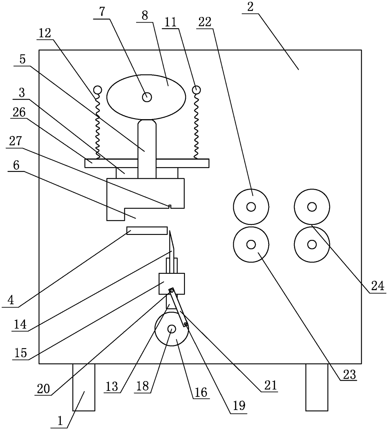
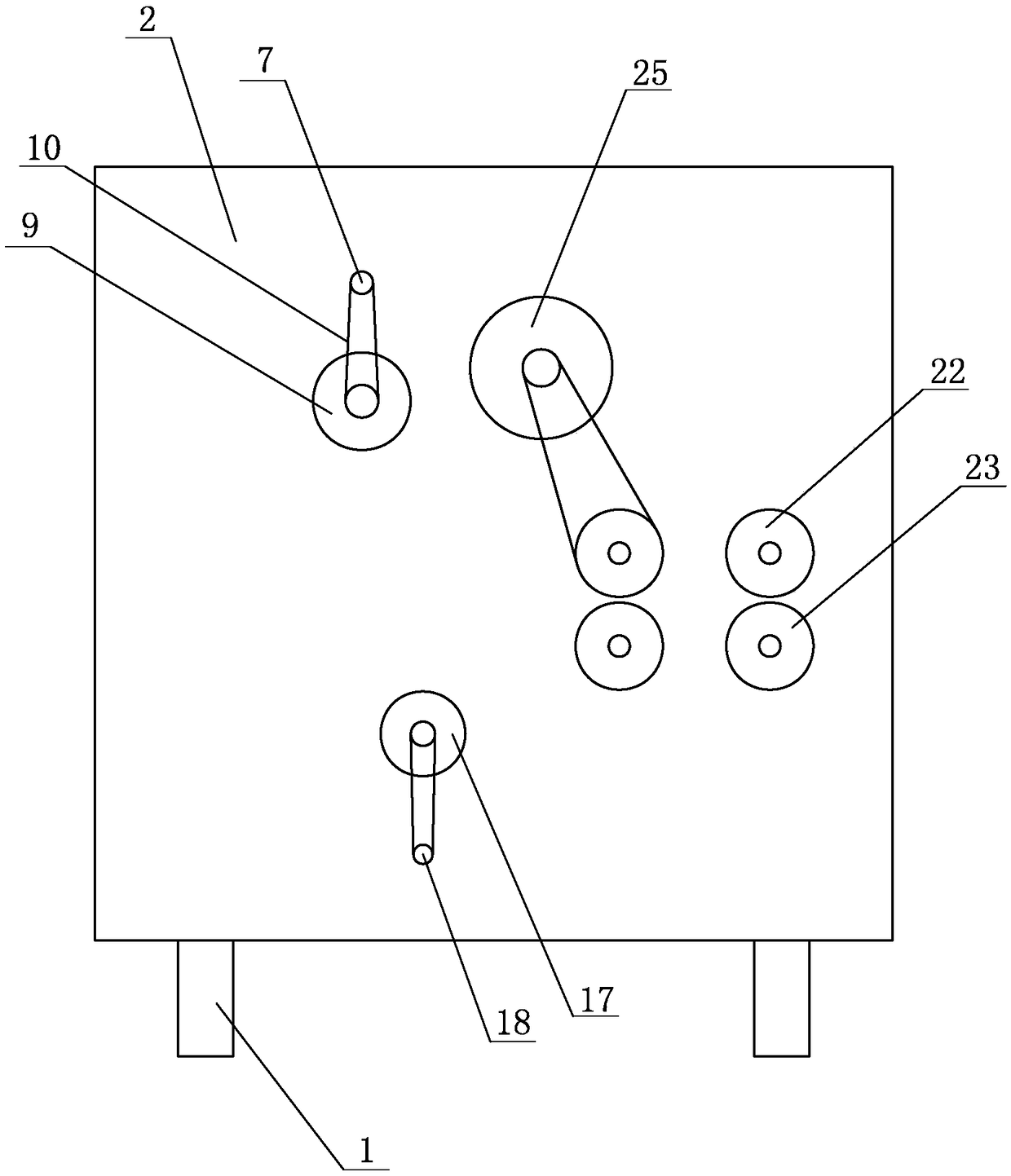
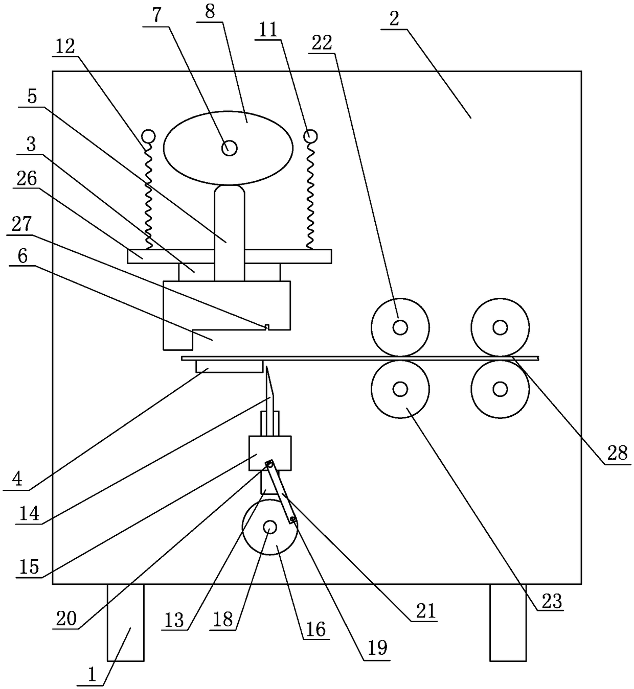
[0018] Embodiment one: see Figure 1-5 As shown, a steel plate bending and cutting device includes a frame 1, a vertical plate 2 arranged on the frame 1, a bending mechanism arranged on the front side of the vertical plate 2, a cutting mechanism and a conveying mechanism, and the conveying mechanism is set On the right side of the bending mechanism, the bending mechanism includes a vertical slide rail 3, a positioning block 4 and a bending block 5, and the vertical slide rail 3 is arranged directly above the positioning block 4, so that The bending block 5 is slidably arranged on the vertical slide rail 3, and a groove 6 is provided at the bottom of the bending block 5, the groove 6 matches the positioning block 4, and the vertical sliding A rotating shaft 7 is provided directly above the rail 3, an oval wheel 8 is provided on the rotating shaft 7, a motor 9 is provided on the rear side of the vertical plate 2, and the output shaft of the motor 9 is connected to the rotating s...


PUM


Abstract

The invention discloses a steel plate bending and cutting device. The device is characterized by comprising a rack, a vertical plate, a bending mechanism, a cutting mechanism and a conveying mechanism; the bending mechanism comprises a vertical sliding rail, a positioning block and a bending block; the bending block is glidingly arranged on the vertical sliding rail; a groove is formed in the bottom of the bending block and is matched with the positioning block; a rotating shaft is arranged above the vertical sliding rail; an elliptic wheel is arranged on the rotating shaft; a limiting bolt isarranged in the position, located on each of two sides of the rotating shaft, of the vertical plate; a spring is arranged on each limiting bolt; the top of each spring is connected with the corresponding limiting bolt; the bottoms of the two springs are connected with the two sides of the bending block; the peripheral surface of the elliptic wheel makes contact with the top of the bending block;and the cutting mechanism is arranged under the right side of the positioning block. By the aid of the steel plate bending and cutting device, the bending and cutting efficiency of products is improved, and the machining safety is improved.

Description

technical field [0001] The invention relates to a steel plate processing equipment, in particular to a steel plate bending and cutting device. Background technique [0002] In the prior art, there are generally two ways to bend the steel plate into an L-shaped structure. The first is to cut the product first, and then the operator puts it into the mold for bending processing; the other is to The bending and cutting is now performed in the mold, and the product is then manually removed from the mold by the operator. These two methods all require operators to manually handle, which is not only inefficient, but also has potential safety hazards during the operation of the operator. Contents of the invention [0003] The object of the present invention is to provide a steel plate bending and cutting device, by using the structure, the bending and cutting efficiency and quality of products are improved. [0004] In order to achieve the above object, the technical solution ado...

Claims


Application Information

Patent Timeline
Patent Type & Authority Applications(China)
IPC IPC(8): B23P13/02B23D27/00B21D5/02
CPCB21D5/02B23D27/00B23P13/02
Inventor 李丽
Owner 苏州裕庆金属制品有限公司
Why Eureka
Try Eureka