Assembling device for stator iron core and stator coil

A technology of stator coils and stator cores, applied in electromechanical devices, metal processing, manufacturing motor generators, etc., can solve problems such as potential safety hazards, low assembly efficiency, and inconvenient placement of stator cores, and achieve safe and reliable devices and high assembly efficiency Improved effect

Pending Publication Date: 2019-02-15
宁波意卡德电器科技有限公司
View PDF0 Cites 1 Cited by
  • Summary
  • Abstract
  • Description
  • Claims
  • Application Information

AI Technical Summary

Problems solved by technology

[0002] The stator core and the stator coil are interference-fitted together to form the stator of the motor. During the assembly process, the stator core needs to be placed in the inner cavity of a bottom mold, and the stator coil is punched into the stator core by stamping. In the current assembly process of the workshop, the bottom mold is generall

Method used


Image

  • Assembling device for stator iron core and stator coil
  • Assembling device for stator iron core and stator coil
  • Assembling device for stator iron core and stator coil

Examples


Embodiment Construction

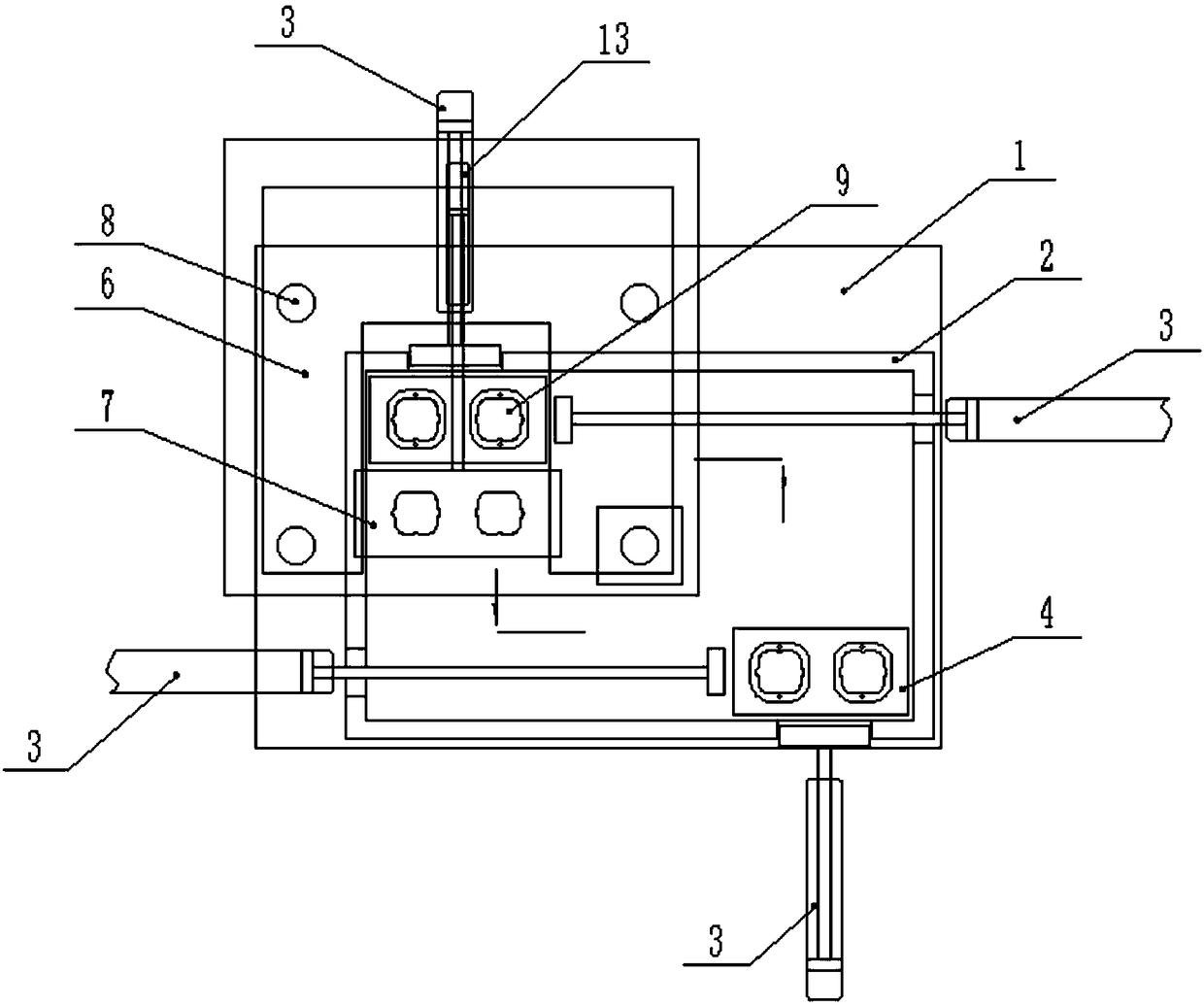
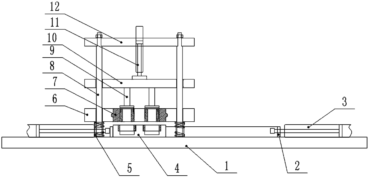
[0030] Such as figure 1 , figure 2 As shown, the assembly device of a stator core and a stator coil described in the embodiment of the present invention includes a workbench 1 on which a rectangular enclosure 2 is fixed, and a pushing cylinder 3 is fixed on the edge of the enclosure 2 At the four end corners; the guide column 8 is fixed on the workbench 1, a total of four guide columns 8 form a rectangle, one of the guide columns 8 is located in the middle of the rectangle surrounded by the hoarding plate 2, and the top of the guide column 8 is a variable diameter section, the upper platform 12 is locked on the variable diameter section by nuts, and a stamping cylinder 11 is installed in the middle of the upper platform 12; the middle platform 10 is located below the upper platform 12 and is guided by the guide column 8, and the upper surface of the middle platform 10 is connected with the stamping cylinder The cylinder shaft of 11 is fixedly connected, and the lower surface...


PUM


Abstract

The invention provides an assembling device for a stator iron core and a stator coil. The device comprises a workbench, a rectangular surrounding plate is fixed to the workbench, pushing air cylindersare fixed at the corners of the surrounding plate, guide stand columns are fixed to the workbench, an upper platform is fixed to the upper ends of the guide stand columns, and a stamping air cylinderis arranged in the middle of the upper platform. A middle platform is located below the upper platform and guided by the guide stand columns, the middle platform is fixedly connected with the stamping air cylinder, a stamping head is fixed to the lower surface of the middle platform, and a lower platform is located above the workbench and below the middle platform. The lower platform is supportedby compression springs, and a sliding block which slides relative to the lower platform is arranged in the lower platform. Through holes matched with the stator coil are machined in the sliding block, a bottom die is arranged in the surrounding plate and pushed by the pushing air cylinders, and an inner cavity is formed in the bottom die. The bottom die moves along the inner side of the surrounding plate under the action of the pushing air cylinders, workers place the stator iron core on the bottom die, the stator coil is placed when the sliding block slides out, the device is safe and reliable, and the assembly efficiency is greatly improved.

Description

technical field [0001] The invention relates to an assembly device of a stator iron core and a stator coil. Background technique [0002] The stator core and the stator coil are interference-fitted together to form the stator of the motor. During the assembly process, the stator core needs to be placed in the inner cavity of a bottom mold, and the stator coil is punched into the stator core by stamping. In the current assembly process of the workshop, the bottom mold is generally fixed under the stamping equipment. After the stator core and stator coil are placed manually, the stamping equipment is controlled to stamp. Only one motor stator can be assembled at a time, and the assembly efficiency is low. Simultaneously, it is inconvenient to place the stator iron core on the bottom mold, and there is also a certain potential safety hazard. Contents of the invention [0003] In view of the deficiencies in the above problems, the present invention provides an assembly device...

Claims


Application Information

Patent Timeline
IPC IPC(8): B23P19/027H02K15/08
CPCH02K15/08B23P19/027
Inventor 蒋能国陈杰
Owner 宁波意卡德电器科技有限公司
Why Eureka
Try Eureka