Clamp for loading and unloading piercer plug

A punching machine and jig technology, applied in the field of punching machines, can solve the problems of single processing effect, poor stability, and poor adaptability, and achieve the effects of convenient and simple replacement, improved stability, and high flexibility

Inactive Publication Date: 2019-02-15
于佳
View PDF1 Cites 8 Cited by
  • Summary
  • Abstract
  • Description
  • Claims
  • Application Information

AI Technical Summary

Problems solved by technology

[0005] 1) Poor stability: When fixing the above solution, the front part of the rotating arm is used to contact the outside of the punching machine head. To be precise, the head is fixed only through two obliquely symmetrical points. Although the structure is simple, the stability is not good. Not ideal, it is very easy to make the fixed head

Method used


Image

  • Clamp for loading and unloading piercer plug
  • Clamp for loading and unloading piercer plug
  • Clamp for loading and unloading piercer plug

Examples


Embodiment Construction

[0024] The present invention will be further described below in conjunction with the accompanying drawings and specific embodiments.

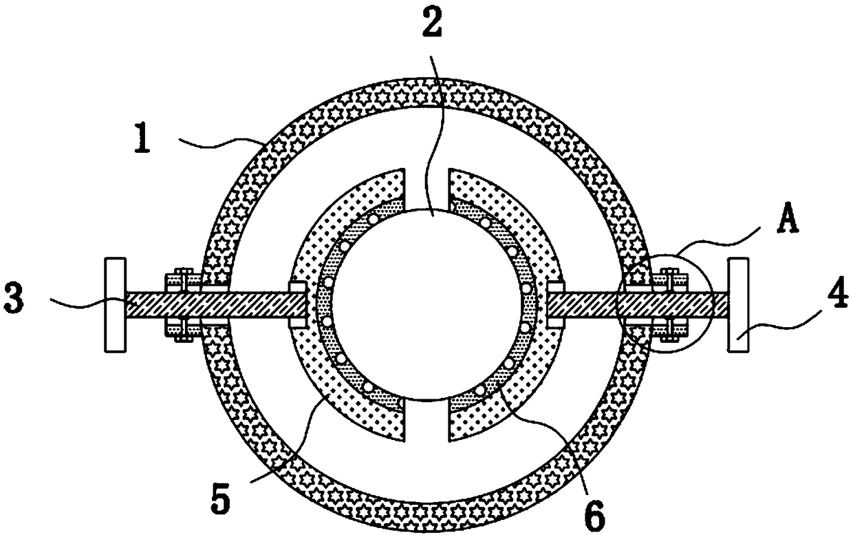
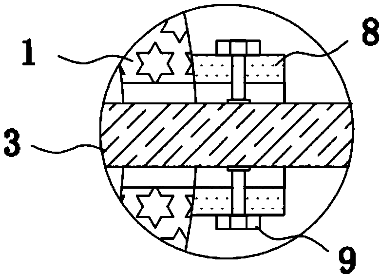
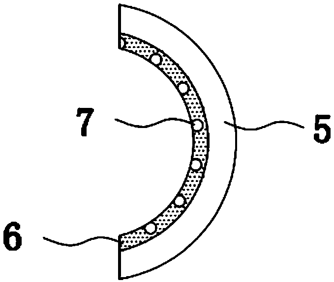
[0025] refer to Figure 1-3 It can be known that a jig for loading and unloading the head of a piercing machine in the present invention includes a fixing ring 1. The inside of the fixing ring 1 is sleeved with a plug body 2 protruding from its lower part. The left and right sides of the fixing ring 1 are screwed with screw rods. 3. The outer end of the screw rod 3 is integrally connected with a rotating hand wheel 4, and the inner end of the screw rod 3 is connected to an arc-shaped splint 5 through bearing rotation, and the inner wall of the arc-shaped splint 5 is evenly glued An anti-slip rubber pad 6 is attached to the outer wall of the plug body 2, and two anti-slip rubber pads 6 are equidistantly provided with U-shaped avoidance grooves 7 on opposite sides. The left and right sides of the outer wall of the fixing ring 1 are also integral...


PUM


Abstract

The invention relates to the technical field of piercers, in particular to a clamp for loading and unloading a piercer plug. The clamp comprises a fixing ring. A plug body extending out of the lower part of the fixing ring is sleeved with the fixing ring. Screw rods are correspondingly screwed on the left side and the right side of the fixing ring. Rotating hand wheels are integrally connected tothe outer ends of the corresponding screw rods. Arc-shaped clamping plates are rotationally connected to the ends in the screw rods through bearings. Anti-skidding rubber pads are adhered to the innerwalls of the arc-shaped clamping plates and are abutted against the outer wall of the plug body. During installation, locking bolts on the front and rear sides of the outer wall of the fixing ring are loosened firstly, and then an operator holds the rotating hand wheels by both hands to make the rotating hand wheels to rotate forward together, so that the distance between the two arc-shaped clamping plates is conveniently shortened, the plug body is fixed in an abutted manner, and the locking bolts on the front and rear sides of the outer wall of the fixing ring are tightened again; and meanwhile, the anti-skidding rubber pads are adhered to the inner walls of the corresponding arc-shaped clamping plates, and the installation and fixation stability of the plug body can be improved throughthe anti-skidding rubber pads.

Description

technical field [0001] The invention relates to the technical field of punching machines, in particular to a jig for loading and unloading the plug of a punching machine. Background technique [0002] At present, each steel pipe factory all adopts manual hammering to take a lot of time when loading and unloading the plugs for steel pipe perforation. The labor intensity is high, the work efficiency is low, and the plugs are easily damaged. [0003] In this regard, the patent application number is CN201420681620.1, which proposes a clamp for loading and unloading the punching machine head. The loading and unloading clamp includes a lever, a rotating arm, a pin shaft and a fixed ring. The fixed ring is installed on the top of the punching machine head. The rotating arm has two Each is fixed and symmetrically connected to the lower part of the fixed ring through pin shafts, the front part of the rotating arm is in contact with the outside of the punching machine head, and the re...

Claims


Application Information

Patent Timeline
IPC IPC(8): B25B27/02
CPCB25B27/023
Inventor 于佳
Owner 于佳
Why Eureka
Try Eureka