Supercharge Your Innovation With Domain-Expert AI Agents!

Four-rotor unmanned aerial vehicle with landing buffering function

A quadrotor UAV and UAV technology, applied in the field of UAV, can solve the problems of affecting the range and speed of UAV, increasing the wind resistance of UAV flight, increasing the development and production cost of UAV, etc. To achieve the effect of prolonging the service life, good use effect and stable landing

Inactive Publication Date: 2019-02-15
深圳市金鑫城纸品有限公司
View PDF0 Cites 2 Cited by
  • Summary
  • Abstract
  • Description
  • Claims
  • Application Information

AI Technical Summary

Problems solved by technology

[0002] At present, the landing gear on the traditional quadrotor UAV does not have a stackable function; during the flight of the UAV, the landing gear without the stacking function increases the flight resistance of the UAV, which in turn affects the unmanned aircraft. range and speed of the aircraft; even if some UAVs have a landing gear with a stacking function, the R&D and production costs of the UAV are increased due to the complexity of the control method of the landing gear; There are generally two ways to control the landing gear: one is to control the hydraulic pump installed on the airframe through a servo motor, and then control the stacking of several landing gears through hydraulic pressure; the other is to control several landing gears through at least two servo motors. The folding of the landing gear; this traditional way of stacking the landing gear also increases the R&D and production costs of UAVs, thus affecting the progress of UAVs being widely used, and thus affecting the economic benefits of related enterprises

Method used


Image

  • Four-rotor unmanned aerial vehicle with landing buffering function
  • Four-rotor unmanned aerial vehicle with landing buffering function
  • Four-rotor unmanned aerial vehicle with landing buffering function

Examples


Embodiment Construction

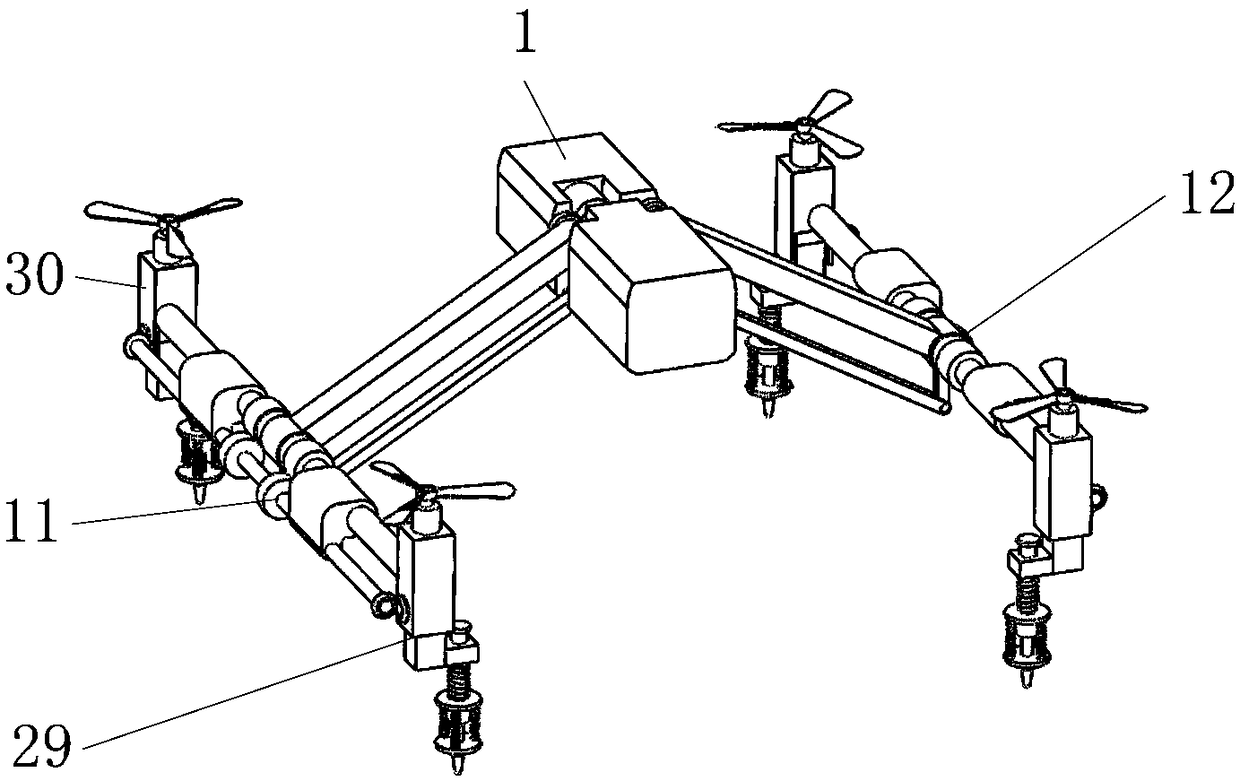
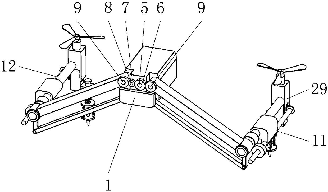
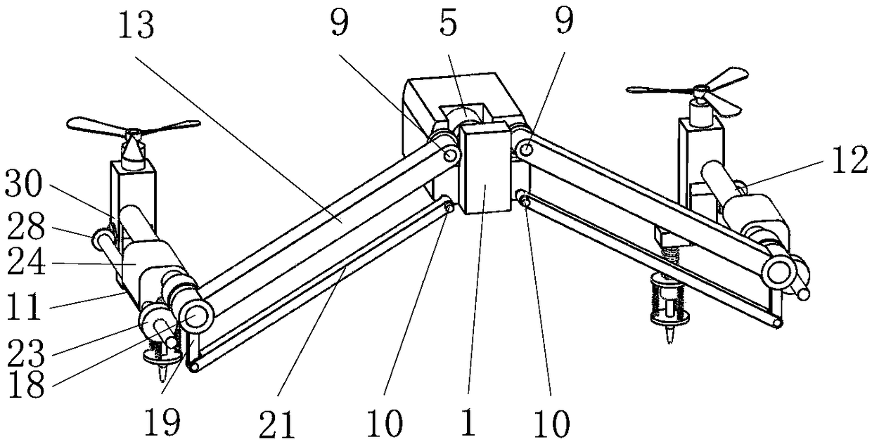
[0037] Such as figure 1 , 2 , 3, it includes a body 1, a steering gear 5, a first rotor mechanism 11, and a second rotor mechanism 12, wherein the body 1 is an existing four-rotor UAV body 1; the first rotor mechanism 11 and the second rotor mechanism The mechanism 12 is symmetrically installed on both sides of the machine body 1 through the corresponding second pin shaft 9 and third pin shaft 10 respectively.

[0038] Such as figure 2 , 5 As shown, the steering gear 5 drives the first rotor mechanism 11 and the second rotor mechanism 12 to swing up and down synchronously through the drive gear 6 installed thereon; and the second rotor mechanism 12 swing upwards along the corresponding second pin shaft 9 and the third pin shaft 10, while the first folding mechanism 29 and the second folding mechanism 30 in the first rotor mechanism 11 and the second rotor mechanism 12 are folded so as to reduce the wind resistance encountered by the UAV during flight, thereby improving th...


PUM


Abstract

The invention belongs to the field of unmanned aerial vehicles, and particularly relates to a four-rotor unmanned aerial vehicle with a landing buffering function. The four-rotor unmanned aerial vehicle includes a vehicle body, a first rotor mechanism and a second rotor mechanism, wherein the first rotor mechanism and the second rotor mechanism are symmetrically mounted on both sides of the vehicle body through a corresponding second pin shaft and a corresponding third pin shaft correspondingly. According to the unmanned aerial vehicle, a first folding mechanism and a second folding mechanismin the first rotor mechanism and the second rotor mechanism are overlapped only through a steering engine; when the unmanned aerial vehicle takes off and lands, the first folding mechanism and the second folding mechanism in the first rotor mechanism and the second rotor mechanism can be retracted; when the unmanned aerial vehicle lands, the first folding mechanism and the second folding mechanismin the first rotor mechanism and the second rotor mechanism have certain buffering functions; and occurrence of the phenomenon of impact damage of gear teeth of a high-speed gear in the steering engine caused by impact of the ground to a second supporting rod when the unmanned aerial vehicle lands is avoided, and then the fact that a driving device on the unmanned aerial vehicle is not damaged isensured.

Description

technical field [0001] The invention belongs to the field of unmanned aerial vehicles, in particular to a quadrotor unmanned aerial vehicle with a landing buffer function. Background technique [0002] At present, the landing gear on the traditional quadrotor UAV does not have a stackable function; during the flight of the UAV, the landing gear without the stacking function increases the flight resistance of the UAV, which in turn affects the unmanned aircraft. range and speed of the aircraft; even if some UAVs have a landing gear with a stacking function, the R&D and production costs of the UAV are increased due to the complexity of the control method of the landing gear; There are generally two ways to control the landing gear: one is to control the hydraulic pump installed on the airframe through a servo motor, and then control the stacking of several landing gears through hydraulic pressure; the other is to control several landing gears through at least two servo motors....

Claims


Application Information

Patent Timeline
IPC IPC(8): B64C27/50B64D45/06
CPCB64C27/50B64D45/06
Inventor 不公告发明人
Owner 深圳市金鑫城纸品有限公司
Features
  • R&D
  • Intellectual Property
  • Life Sciences
  • Materials
  • Tech Scout
  • Unparalleled Data Quality
  • Higher Quality Content
  • 60% Fewer Hallucinations
Learn More