


Quick Research
Generate reliable direction feasibility study reports for your R&D in just a few steps.

Technical Q&A
Discover and master advanced knowledge NOW. Basics, ideas, possibilities, all at once.

Find Solutions
As an expert in R&D theories, this can generate solutions to your technical problems instantly.

Evaluate Feasibility
Analyze your overall solution with one click, know your potential R&D risks in advance.

Monitor Landscape
Get weekly tech updates, stay abreast of the latest tech innovations and key insights.
A wall-mounted siphon toilet
A toilet and siphon technology, applied in the field of bathroom, can solve the problems of high cost of flush valve, unsuitable for ordinary household use, high flushing noise, unsuitability, etc., and achieve the effects of improving drainage efficiency, improving flushing performance and saving water.
- Summary
- Abstract
- Description
- Claims
- Application Information
AI Technical Summary
Problems solved by technology
Method used
Image

Examples
Embodiment 1
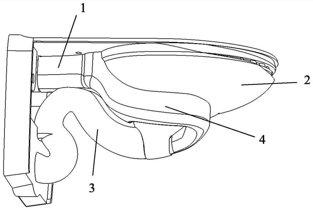
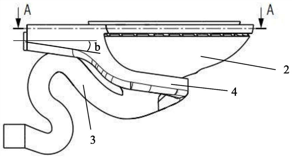
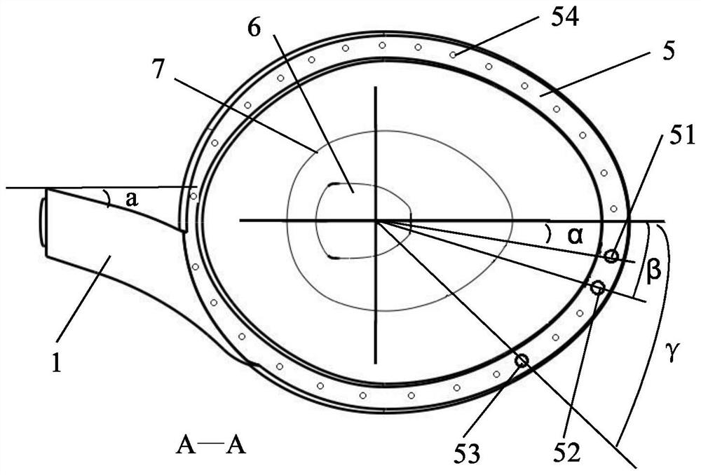
[0048] refer to Figure 1 to Figure 10, a wall-mounted siphon toilet, including a water inlet 1, a toilet cylinder 2 and a siphon pipe 3, the water inlet 1 is oblique to the side of the toilet, and the preferred range of the angle a between the water inlet 1 and the vertical plane Between 10 degrees and 20 degrees, a water diversion port 8 is provided at the end of the water inlet 1, and the water diversion port 8 is connected with the auxiliary water channel 4 and the water circle water channel 5, and the water flow passes through the water inlet 1 to reach the water inlet 8 , due to the fact that the water flow has a certain flow rate and has the effect of gravity at the same time, part of the water flow will continue to flow into the water circle channel 5 along the original flow direction due to inertia, and the other part sinks at the water diversion port 8 and flows into the auxiliary water channel due to gravity 4. More preferably, the water inlet 1 has a sinking design...
Embodiment 2
[0050] Such as Figure 11 and Figure 15 As shown, the difference between this embodiment and Embodiment 1 is that there is no second water guiding surface at the end of the upper S section of the descending section 32 of the siphon pipe 3, and the right pipe surface of the upper S section of the descending section 32 is in contact with the The tangent point in the vertical direction is the left end point L of the upper S section of the descending section 32, and the tangent point between the left pipe surface of the lower S section of the descending section 32 and the vertical direction is the lower S section of the descending section 32. The right end point R, the left end point L of the upper S section of the descending section 32 is on the left side of the right end point R of the lower S section of the descending section 32, this design can effectively prevent the air in the drain from flowing back into the siphon pipe to destroy the siphon, Thereby improving the siphon ...
Embodiment 3
[0052] Such as Figure 16 and Figure 18 As shown, the difference between this embodiment and Embodiment 1 and Embodiment 2 is that an air passage 10 is provided between the auxiliary water channel 4 and the water ring water channel 5, and the air passage is located in the toilet cylinder 2 The outer wall of the outer wall, the lower end of the air channel 10 communicates with the auxiliary water channel 4, the upper end of the air channel 10 communicates with the water circle water channel 5, and the air channel 10 is located at the arc section of the water circle water channel 5 to be connected with the The connecting part of the water inlet 1 is one-tenth to one-fifth of the starting point. When draining, the air in the auxiliary water channel 4 can be discharged through the air channel 10, thereby increasing the water flow velocity and improving the siphon efficiency.
[0053] Combine below Figure 10 and Figure 15 Specify the direction of water flow in the toilet.
...
PUM
 Abstract
Description
Claims
Application Information
 - R&D Engineer
- R&D Manager
- IP Professional
- Industry Leading Data Capabilities
- Powerful AI technology
- Patent DNA Extraction
Browse by: Latest US Patents, China's latest patents, Technical Efficacy Thesaurus, Application Domain, Technology Topic, Popular Technical Reports.
© 2024 PatSnap. All rights reserved.Legal|Privacy policy|Modern Slavery Act Transparency Statement|Sitemap|About US| Contact US: help@patsnap.com