Water spraying structure for water closet, and water closet

A technology for toilets and bedpans, which is applied in the field of water spray structures and toilets, and can solve the problems of affecting the instantaneous flow rate of injection nozzles and weakening flushing force, so as to achieve good sewage discharge effect, improve flushing force, and increase the effect of instantaneous flow rate

Inactive Publication Date: 2019-01-29
KOHLER CHINA INVESTMENT
View PDF5 Cites 4 Cited by
  • Summary
  • Abstract
  • Description
  • Claims
  • Application Information

AI Technical Summary

Problems solved by technology

At present, the toilet spray nozzles on the market are generally cylindrical with equal diameters, some are rectangular or elliptical, and the entrance and exit cross-sectional areas of the spray nozzles are all the same in shape, and some spray nozzles and toilets are later Assembled, the exit section of the injection nozzle is smaller than the entry section, presenting a constricted nozzle
The inventor finds that there are at least the following problems in the prior art: the length of the nozzle is generally the ceramic wall thickness of the toilet, and the length of the nozzle is not long enough, so the energy of the outlet of the nozzle is determined by the height from the water level line in the water tank to the outlet of the nozzle. Provided potential energy, so when the nozzle is flushing the bedpan, the air can easily enter the injection pipe through the nozzle to break the vacuum, which will affect the instantaneous flow of the nozzle and weaken the flushing force of the nozzle on the bedpan

Method used


Image

  • Water spraying structure for water closet, and water closet
  • Water spraying structure for water closet, and water closet
  • Water spraying structure for water closet, and water closet

Examples


Embodiment Construction

[0028] In order to make the purpose, technical solutions and advantages of the embodiments of the present invention more clear, various implementation modes of the present invention will be described in detail below in conjunction with the accompanying drawings. However, those of ordinary skill in the art can understand that, in each implementation manner of the present invention, many technical details are provided for readers to better understand the present application. However, even without these technical details and various changes and modifications based on the following implementation modes, the technical solution claimed in this application can also be realized.

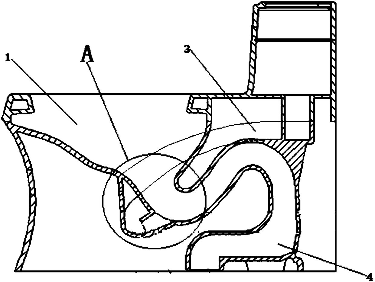
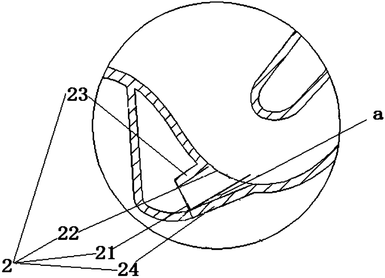
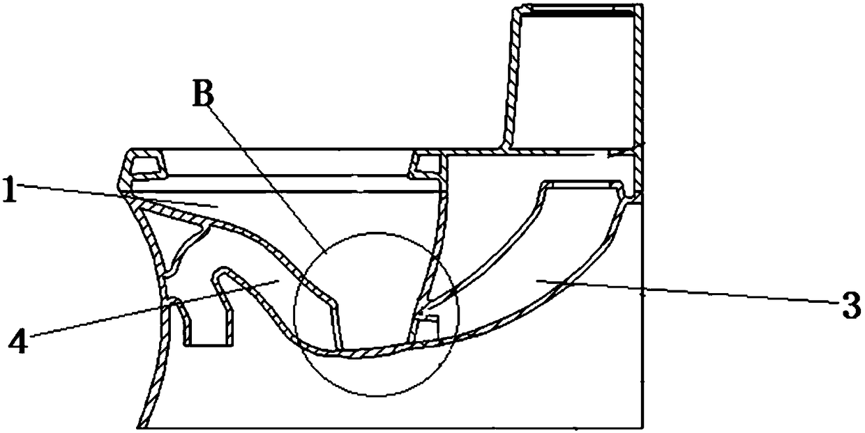
[0029] The first embodiment of the present invention relates to a water spray structure of a toilet, such as figure 1 As shown, it includes a spray nozzle 2 arranged on a toilet pan body 1 . Wherein, the spray nozzle 2 is connected with the spray water pipe 3 of the toilet, so that the dirt in the toilet bo...


PUM


Abstract

The invention relates to sanitary and bathroom equipment, and particularly relates to a water spraying structure for a water closet, and the water closet. An injection nozzle includes an injection outlet and an injection inlet that communicates with the injection outlet, and the linear distance from the injection outlet to the injection inlet is larger than the cross-sectional diameter of the injection inlet, and so, when an injection water pipe flushes the inside of a bedpan body through the injection nozzle, a certain degree of vacuum can be generated between the injection inlet and the injection outlet under the action of water flow, so that the energy at the injection outlet of the injection nozzle is the sum of the potential energy generated by the height of a water level line of a water tank to the injection outlet of the injection nozzle and the energy that generates the degree of vacuum in the injection nozzle, and further the instantaneous flow rate at the injection outlet ofthe injection nozzle can be effectively increased. Compared with the prior art, the water spraying structure can not only effectively improve the flushing strength of the injection nozzle on the bedpan body, but also ensure better drainage effect on the bedpan body while ensuring usage of less flushing water, and can achieve the purpose of saving water.

Description

technical field [0001] The invention relates to sanitary equipment, in particular to a water spray structure of a toilet and the toilet. Background technique [0002] The toilet, as a kind of sewage device, its basic principle is to use the gravity of water to convert the potential energy of water into the kinetic energy of water, so as to carry the excreted dirt into the sewer pipe to complete the whole process of sewage discharge. Moreover, with the advancement of science and technology, the water closet has also developed from the most primitive manual type to today's electric type. [0003] And existing toilet, no matter manual type or electric type, after the flushing valve in the water tank is opened, enters in the spraying water pipe that is connected with it along with flushing pipeline, and sprays out from spraying nozzle, is used to make sewage pipeline generate waste water. The siphon takes away the dirt in the basin. At present, the toilet spray nozzles on the ...

Claims


Application Information

Patent Timeline
Patent Type & Authority Applications(China)
IPC IPC(8): E03D9/08E03D11/13
CPCE03D9/08E03D11/13E03D2201/30
Inventor 马凌骏赵松原
Owner KOHLER CHINA INVESTMENT
Why Eureka
Try Eureka