Roller pin lubricating-type casing pipe truss having self-locking anti-falling structure

A technology of anti-dropping and needle rolling, which is applied in the direction of machine/support, supporting machine, mechanical equipment, etc., can solve the problems of inconvenient use of manual lifting or opening and closing devices, takes up a large space, and increases the complexity of the structure. Firm and reliable, enhanced truss applicability, smooth and unimpeded relative movement

Inactive Publication Date: 2019-02-15
CHANGZHOU COLLEGE OF INFORMATION TECH
View PDF0 Cites 2 Cited by
  • Summary
  • Abstract
  • Description
  • Claims
  • Application Information

AI Technical Summary

Problems solved by technology

[0003] Most of the current trusses are designed and manufactured without considering the need for elongation or shortening. The support needs to be raised or lowered, and the approach or distance is often realized by other electric and manual structures. The truss still only serves as a support for a fixed position. In this way, the truss and other lifting devices will greatly increase the complexity of the structure, take up a lot of space, and it is not convenient to use manual lifting or opening and closing devices.

Method used


Image

  • Roller pin lubricating-type casing pipe truss having self-locking anti-falling structure
  • Roller pin lubricating-type casing pipe truss having self-locking anti-falling structure
  • Roller pin lubricating-type casing pipe truss having self-locking anti-falling structure

Examples


Embodiment Construction

[0031]The following will clearly and completely describe the technical solutions in the embodiments of the present invention with reference to the accompanying drawings in the embodiments of the present invention. Obviously, the described embodiments are only some, not all, embodiments of the present invention. Based on the embodiments of the present invention, all other embodiments obtained by persons of ordinary skill in the art without making creative efforts belong to the protection scope of the present invention.

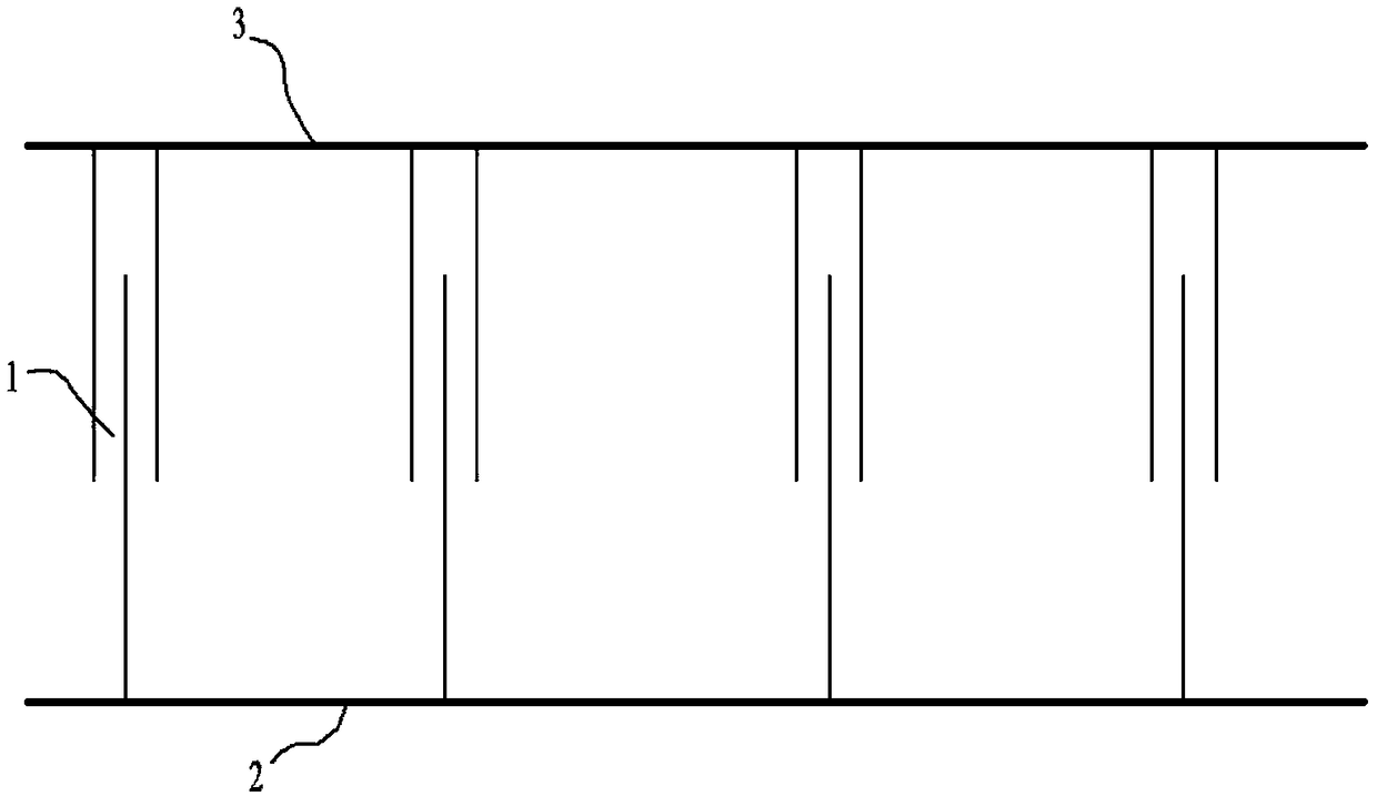
[0032] Such as figure 1 As shown, the casing truss includes several casings 1 , lower trusses 2 and upper trusses 3 ; The upper and lower trusses are connected through the casing 1, and the casing 1 can be stretched and contracted to realize the drawing and pulling of the upper and lower trusses, which is suitable for trusses that need to be changed in length or can be retracted.

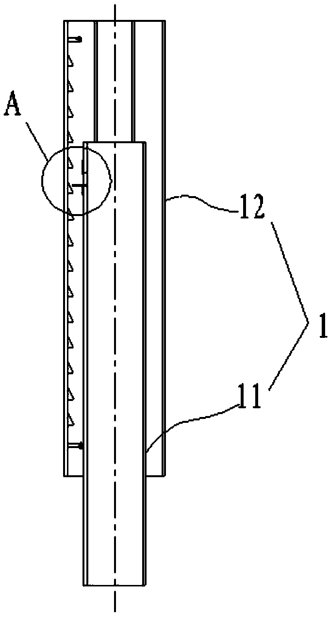
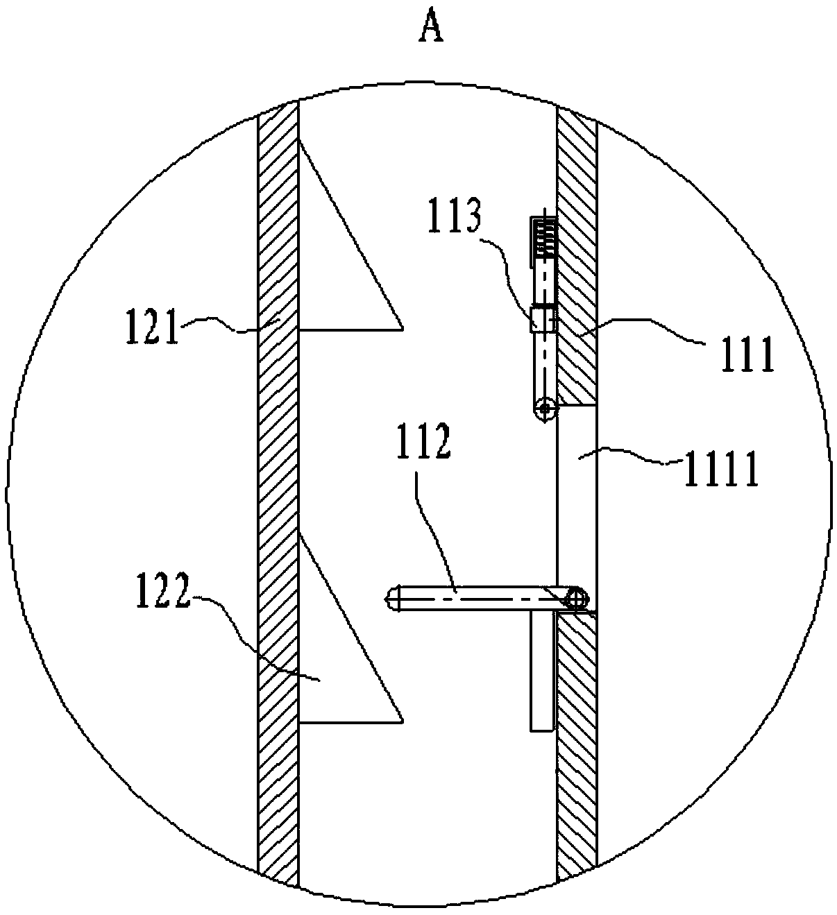
[0033] Such as figure 2 As shown, the casing 1 includes an inner tube assembl...


PUM


Abstract

The invention discloses a roller pin lubricating-type casing pipe truss having a self-locking anti-falling structure. The roller pin lubricating-type casing pipe truss comprises a plurality of casingpipes, a lower truss and an upper truss; the upper ends of the casing pipes are connected with the upper truss; the lower ends of the casing pipes are connected with the lower truss; the upper truss and the lower truss are connected together through the casing pipes; each casing pipe comprises an outer pipe and an inner pipe; the inner pipe and the outer pipe are correspondingly provided with parts: step teeth, a right-angle transition board assembly, a lifting bar and the like; the parts can be used for realizing locking and slip prevention of the inner pipe and the outer pipe at a certain position; and roller pins are also arranged between the inner pipe and the outer pipe so as to guarantee that the inner pipe and the outer pipe move smoothly when sliding relatively. The roller pin lubricating-type casing pipe truss disclosed by the invention is of a mechanical structure, and has a reliable self-locking function; the casing pipes can be stretched to different lengths within a use range and are locked, i.e., the upper truss can remain at several heights within the use range, so that applicability of the truss is greatly enhanced; when the truss is retracted, only the upper trussneeds to be pulled to a highest position; then, pulling the upper truss for one height distance is continued; and then, the truss can be downwards retracted to a lowest position; operation is simple;and the multiple casing pipes are arranged between the upper truss and the lower truss, so that the structure is firm and reliable.

Description

technical field [0001] The invention relates to the field of mechanical support structures, in particular to a needle-lubricated casing truss with a self-locking anti-falling-off structure. Background technique [0002] The truss is usually called: a support structure composed of rods connected by welding, riveting or bolts. The truss mainly bears tension or pressure. Under the premise of achieving the same support force, compared with other types of support methods, the truss structure can be Significantly saves material and reduces the weight of the supporting structure. [0003] Most of the current trusses are designed and manufactured without considering the need for elongation or shortening. The support needs to be raised or lowered, and the approach or distance is often realized by other electric and manual structures. The truss still only serves as a support for a fixed position. In this way, the truss and other lifting devices will greatly increase the complexity of...

Claims


Application Information

Patent Timeline
Patent Type & Authority Applications(China)
IPC IPC(8): F16M11/00
CPCF16M11/00
Inventor 莫盛秋
Owner CHANGZHOU COLLEGE OF INFORMATION TECH
Why Eureka
Try Eureka