
Slag discharge test device for spiral drill rod

A technology of auger rods and testing devices, which is applied in the direction of measuring devices, testing of mechanical components, testing of machine/structural components, etc., can solve the problems of no equipment, detection of auger rod slagging ability, etc., and achieve the effect of reducing actions

Active Publication Date: 2019-02-15
CHONGQING UNIV OF ARTS & SCI
View PDF3 Cites 0 Cited by
  • Summary
  • Abstract
  • Description
  • Claims
  • Application Information

AI Technical Summary

Problems solved by technology

[0002] At present, the various auger drill pipes used in coal mines are estimated for their slag discharge capacity, and there is no specific equipment to detect the slag discharge capacity of various auger drill pipes.

Method used


Image

  • Slag discharge test device for spiral drill rod
  • Slag discharge test device for spiral drill rod
  • Slag discharge test device for spiral drill rod

Examples


Embodiment Construction

[0031] Hereinafter, preferred embodiments of the present invention will be described in detail with reference to the accompanying drawings. It should be understood that the preferred embodiments are only for illustrating the present invention, but not for limiting the protection scope of the present invention.

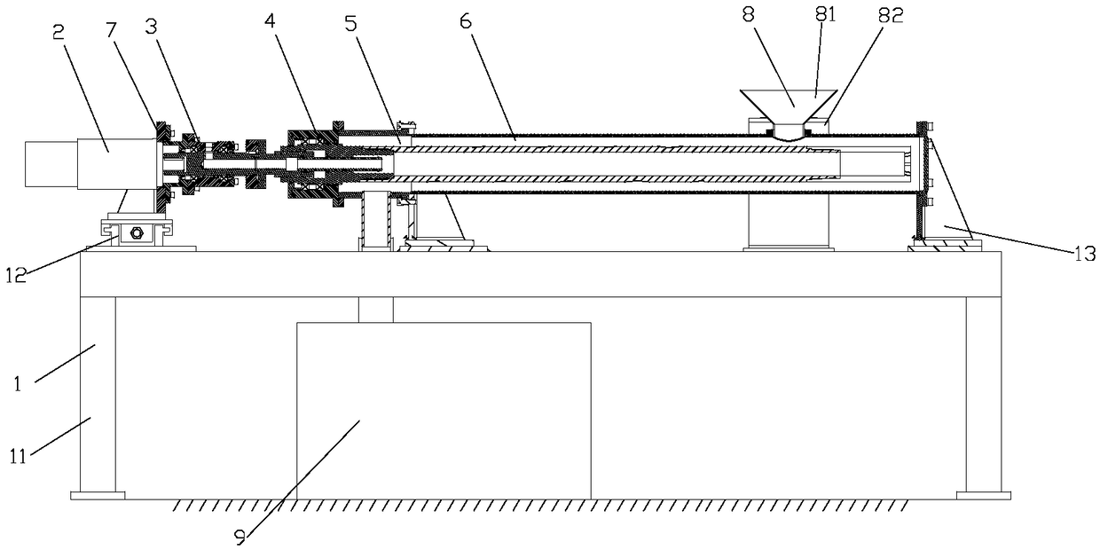
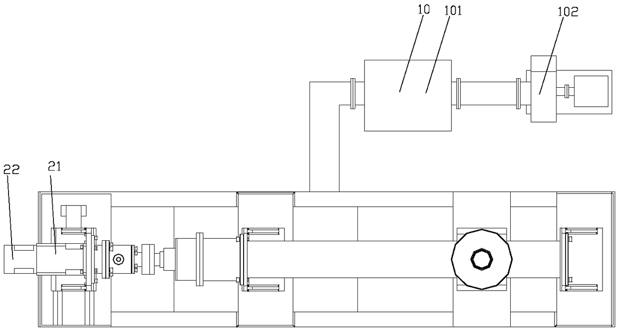
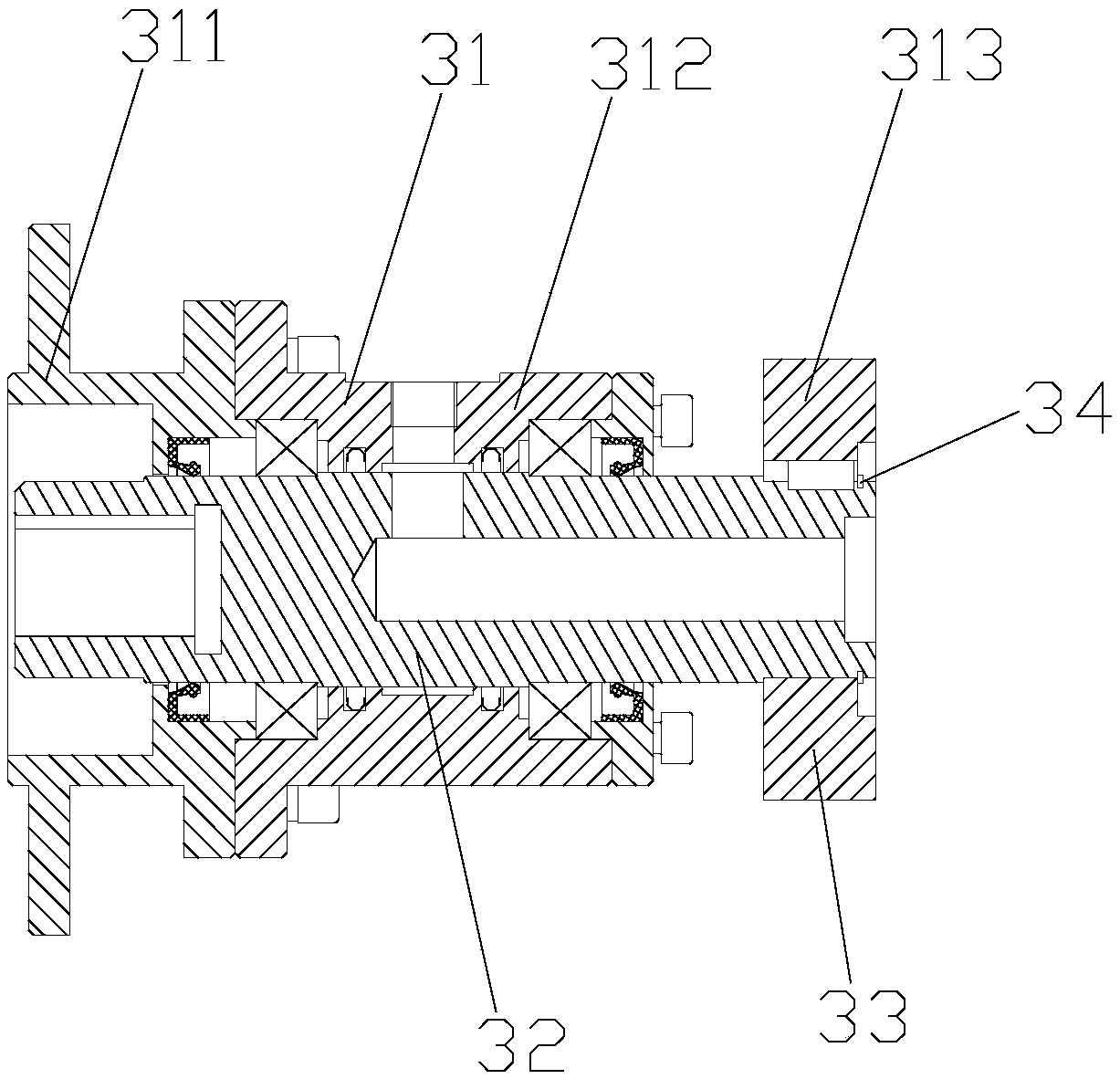
[0032] Such as Figure 1-5 As shown, the auger pipe slag discharge test device includes an underframe 1, on which a power mechanism 2, a gas distribution mechanism 3, a transmission mechanism 4, a discharge mechanism 5 and a test cylinder 6 are sequentially arranged from left to right;

[0033] The base frame 1 includes a frame body 11, on which a sliding mechanism 12 convenient for sliding the power mechanism 2 and two sockets 13 for fixing the test cylinder 6 are arranged in turn from left to right on the frame body 12, and a power seat is arranged on the sliding mechanism 12 7. The left side of the power seat 7 is connected with the power mechanism 2, and the right...


PUM


Abstract

The invention discloses a slag discharge test device for a spiral drill rod. The device comprises a bottom frame; a power mechanism, a gas distribution mechanism, a transmission mechanism, a discharging mechanism and a test cylinder are arranged on the bottom frame sequentially from left to right; the gas distribution mechanism comprises a gas distribution sleeve and a rotating shaft; the transmission mechanism comprises a transmission shell and a transmission shaft; and the transmission shaft comprises an outer shaft, an inner shaft arranged in the outer shaft in a sliding mode, and a ventilation cylinder. A sliding mechanism is arranged, so that different spiral drill rods can be replaced conveniently; the gas distribution mechanism and the transmission mechanism are staggered, so that the transmission mechanism can be conveniently detached, and the spiral drill rod can be conveniently taken out; a slidable inner shaft is arranged on the transmission mechanism, so that the gas distribution mechanism and the transmission mechanism can be conveniently connected; power is transmitted to the transmission mechanism through the gas distribution mechanism, so that the spiral drill rod is driven to rotate; and by arranging a cloth bag type dust remover, the influence on an indoor environment due to the fact that dust leaks into a room from a material collecting box is avoided.

Description

technical field [0001] The invention belongs to the technical field of drill pipe detection equipment, and in particular relates to an auger drill pipe slag discharge test device. Background technique [0002] At present, the various auger drill pipes used in coal mines all estimate the slag discharge capacity of the drill pipes, and there is no specific equipment to detect the slag discharge capacity of various auger drill pipes. Contents of the invention [0003] In view of this, the object of the present invention is to provide a kind of auger rod slag discharge test device, when changing different auger rods by setting a sliding mechanism, the gas distribution mechanism and the transmission mechanism are staggered to facilitate the removal of the transmission mechanism, and the The auger rod is taken out; by setting a slidable inner shaft on the transmission mechanism, it is convenient to connect the gas distribution mechanism and the transmission mechanism, and the po...

Claims


Application Information

Patent Timeline
IPC IPC(8): G01M13/00
CPCG01M13/00
Inventor 唐大勇
Owner CHONGQING UNIV OF ARTS & SCI
Learn More