A cross-sectional design method of automobile body beam based on model validation technology

A design method and technology for body beams, applied in design optimization/simulation, calculation, special data processing applications, etc., to achieve the effect of shortening the design and processing cycle

Pending Publication Date: 2019-02-15
BEIJING MECHANICAL EQUIP INST
View PDF2 Cites 3 Cited by
  • Summary
  • Abstract
  • Description
  • Claims
  • Application Information

AI Technical Summary

Problems solved by technology

[0005] In view of the above analysis, the embodiment of the present invention aims to provide a method for designing a body beam section based on model validation technolo...

Method used


Image

  • A cross-sectional design method of automobile body beam based on model validation technology
  • A cross-sectional design method of automobile body beam based on model validation technology
  • A cross-sectional design method of automobile body beam based on model validation technology

Examples


Embodiment 1

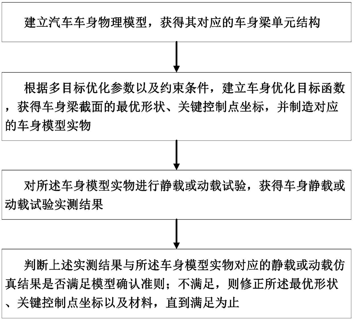
[0060] A specific embodiment of the present invention discloses a method for designing a body beam section based on model validation technology, such as figure 1 shown, including the following steps:

[0061] S1. Establish a physical model of the automobile body and obtain its corresponding body beam unit structure.

[0062] S2. According to the multi-objective optimization parameters and constraints, establish the body optimization objective function, obtain the optimal shape of the body beam section, the coordinates of key control points, and manufacture the corresponding body model. The establishment of the vehicle body optimization objective function aims to optimize the performance of the vehicle body and minimize the cost.

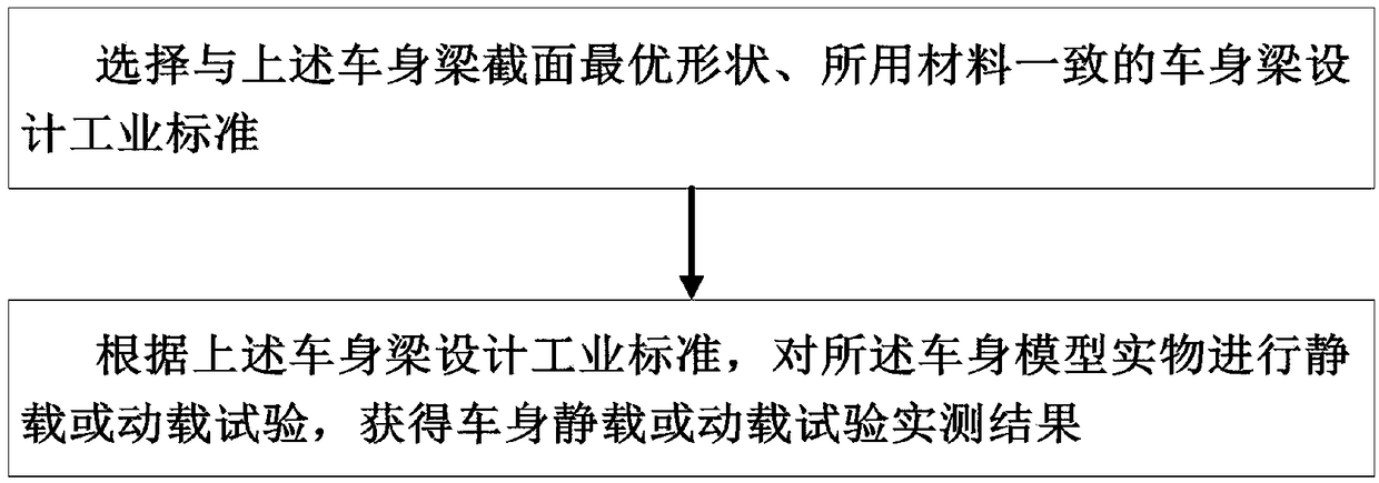
[0063] S3. Perform a static or dynamic load test on the vehicle body model in accordance with industrial design standards, and obtain actual measurement results of the vehicle body static or dynamic load test.

[0064] S4. Judging whether the above...

Embodiment 2

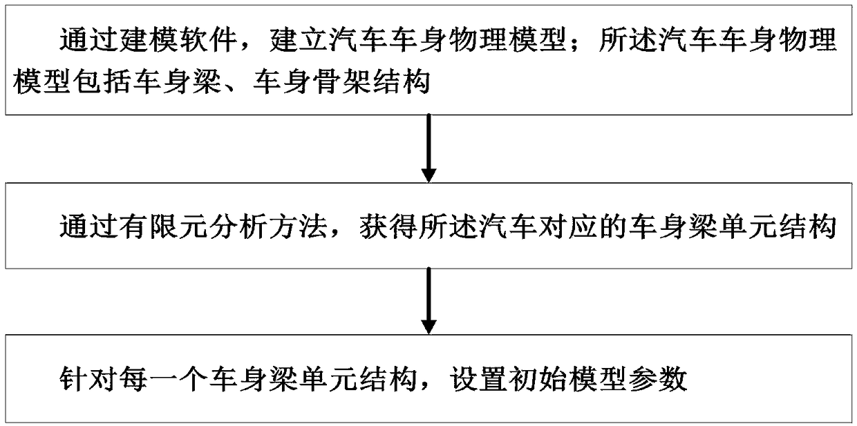
[0067] Optimizing on the basis of the above examples, such as figure 2 As shown, step S1 can be further refined into the following steps:

[0068] S11. According to preset requirements, a physical model of the vehicle body is established through modeling software. The physical model of the automobile body includes a body beam, a body skeleton structure, and the like.

[0069] S12. Carrying out finite element analysis on the physical model of the automobile body by means of finite element analysis method to obtain the corresponding body beam unit structure of the automobile.

[0070] S13. For each body beam unit structure, set initial model parameters. The initial model parameters include material parameters and wall thickness, wherein the material parameters include elastic modulus, Poisson's ratio, density and the like.

[0071] Preferably, in step S2, the multi-objective optimization parameters include body girder sectional area, y-axis moment of inertia, z-axis moment o...


PUM


Abstract

The invention relates to a cross-sectional design method of an automobile body beam based on model confirmation technology, belonging to the technical field of vehicle body cross-sectional design, which solves the problem that the prior art cannot credibly combine numerical modeling simulation and experimental verification for the cross-sectional design of the vehicle body beam. The method comprises the following steps: establishing a physical model of an automobile body; According to the multi-objective optimization parameters and constraint conditions, the body optimization objective function is established to obtain the optimal shape of the body beam section and the coordinates of the critical control points, and the corresponding body model is manufactured. Carrying out static or dynamic load tests on the vehicle body model; Judging whether the static load or dynamic load simulation results corresponding to the actual vehicle body model meet the model validation criteria; If it isnot satisfied, the optimal shape, critical control point coordinates and material are corrected until it is satisfied. The invention forms a numerical analysis cycle period combining theory with practice, which can make the design result of a vehicle body closer to reality and effectively shorten the design and processing cycle.

Description

technical field [0001] The invention relates to the technical field of vehicle body section design, in particular to a method for designing a vehicle body beam section based on model confirmation technology. Background technique [0002] In the process of modern body design, CAE technology is often used for early evaluation of body performance. However, in the concept design stage of the body, most of the body models used for body performance evaluation are simplified frame models composed of beam elements with defined parameters, and the detailed parameters of the body section cannot be defined. It becomes the bottleneck in the development of the smooth transition from the wireframe model of the body concept design to the body design model defined by the surface. [0003] The cross-sectional shape of the body beam directly affects the collision safety of the car. In order to improve the side collision strength of the vehicle body, it is necessary to add a reinforcement pla...

Claims


Application Information

Patent Timeline
IPC IPC(8): G06F17/50
CPCG06F30/15G06F30/23
Inventor 刘杰白鹏英
Owner BEIJING MECHANICAL EQUIP INST
Why Eureka
Try Eureka