Computer input equipment and method

An input device and computer technology, applied in the input/output of user/computer interaction, calculation, input/output process of data processing, etc., can solve problems such as key failure, hair, dust entry, keycap detachment, etc., to avoid damage effect

Pending Publication Date: 2019-02-15
华研科技(大连)有限公司
View PDF0 Cites 1 Cited by
  • Summary
  • Abstract
  • Description
  • Claims
  • Application Information

AI Technical Summary

Problems solved by technology

[0003] During the use of the keyboard in the prior art, hair, dust, etc. may enter the inside of the keyboard due to excessive use time, which may cause the key hole to be blocked, causing the key to fail, and when the user uses the keyboard When the keycap and the pressure pin are socketed together, the keycap may be separated from the pressure pin when the key is popped up, which may cause the keycap to be lost and make the keyboard unusable

Method used


Image

  • Computer input equipment and method
  • Computer input equipment and method
  • Computer input equipment and method

Examples


Embodiment 1

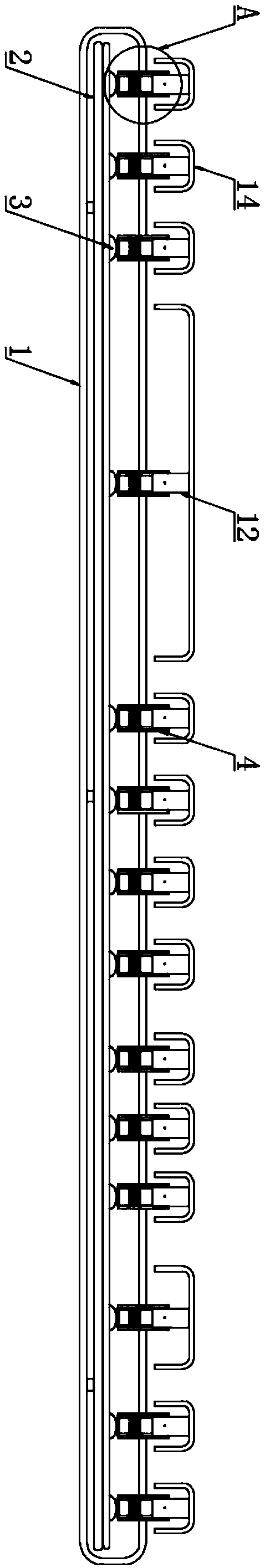
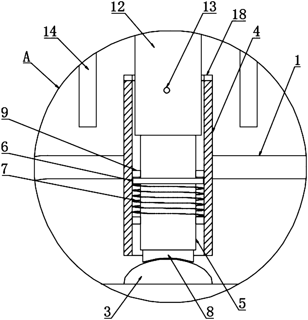
[0029] The present invention provides such Figure 1-4 The shown computer input device includes a casing 1, a circuit board 2 is arranged inside the casing 1, the circuit board 2 is riveted with the casing 1, a rubber cap 3 is arranged on the top of the circuit board 2, and the rubber cap 3. A key hole 4 is provided on the top, and a pressure needle 5 is arranged inside the key hole 4. The pressure needle 5 is slidably connected with the key hole 4. The outer wall of the pressure needle 5 is provided with a snap ring 6. The snap ring 6 The bottom of the ring 6 is provided with a spring 7, the bottom of the pressure needle 5 is provided with a contact head 8, the inner wall of the key hole 4 is provided with a limit ring 9, and the two sides of the inner wall of the key hole 4 are provided with a docking mechanism 10. The inner wall of the top of the key hole 4 is provided with a positioning ring 11, the top of the pressure needle 5 is provided with a pin 12, and the pin 12 is ...

Embodiment 2

[0039] A computer input method, including the computer input device, also includes the following methods:

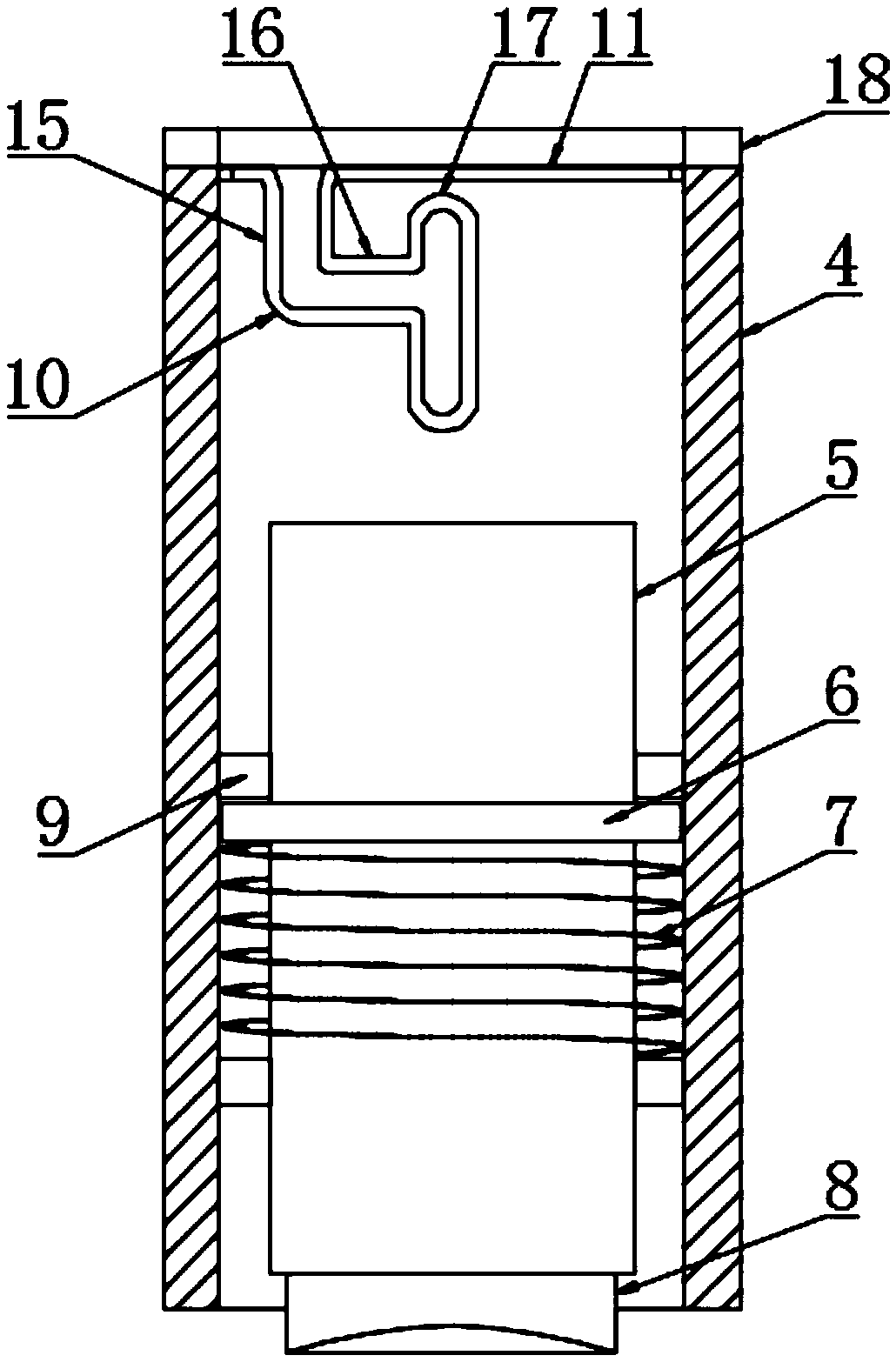
[0040] S1: Insert the pin 12 into the key hole 4, and the positioning ring 11 makes the pin 12 stuck on the top of the key hole 4;

[0041] S2: Turn the keycap 14 to make the pin 12 rotate in the key hole 4;

[0042] S3: When the fixed block 13 rotates above the docking slideway 15, the pin 12 can continue to go deep into the key hole 4, which makes the fixed block 13 move down along the docking slideway 15;

[0043] S4: When the fixed block 13 moves to the bottom of the docking slideway 15, the bottom end of the pin 12 will touch the top of the pressure pin 5, and the pressure pin 5 will move downward, so that the snap ring 6 will also move downward, so that the spring 7 shrink;

[0044] S5: Then turn the keycap 14 to make the pin 13 rotate in the key hole 4, so that the fixed block 13 will move along the horizontal slideway 16;

[0045] S6: When the fixed block 13 m...


PUM


Abstract

The invention discloses computer input equipment and method. The computer input equipment comprises a shell, wherein a circuit board is arranged in the shell and is riveted with the shell, a rubber cap is arranged at the top of the circuit board, a key hole is formed in the top of the rubber cap, a pressure needle is arranged in the key cap and is connected with the key hole in a sliding way, a clamping ring is arranged at an outer wall of the pressure needle, a spring is arranged at the bottom of the clamping ring, and a contact is arranged at the bottom of the pressure needle. By arranging an abutting mechanism, a fixed block, the key hole and the spring, hair, dust and the like can be prevented from entering the computer input equipment due to application for a long time when the computer input equipment is used, the key hole cannot be blocked, so that a key is prevented from being failure; and meanwhile, the key cap cannot fall off from the computer input computer during the application process, the key cap cannot be lost, so that the computer input computer can be normally used.

Description

technical field [0001] The invention relates to the technical field of computer accessories, in particular to a computer input device and method. Background technique [0002] The keyboard is an instruction and data input device used to operate the equipment. It is the most commonly used and most important input device. Through the keyboard, English letters, numbers, punctuation marks, etc. can be input into the computer, so as to issue commands to the computer. Input data, etc., there are many types of keyboards, which can generally be divided into three categories: contact type, non-contact type and laser type. The former uses metal to connect or disconnect two contacts to input signals, and the latter uses metal to input signals. Because Hall effect switches (using changes in magnetic field) and capacitive switches (using changes in current and voltage) generate input signals, computers are generally equipped with keyboards to facilitate human operation of the computer. ...

Claims


Application Information

Patent Timeline
Patent Type & Authority Applications(China)
IPC IPC(8): H01H13/705H01H13/88G06F3/02
CPCH01H13/705G06F3/0202H01H13/88H01H2231/002
Inventor 白井奎
Owner 华研科技(大连)有限公司
Why Eureka
Try Eureka