
Color light lamp drive circuit and drive method thereof

A driving circuit and colored light technology, which is applied to the layout of electric light circuits, light sources, electric light sources, etc., can solve the problems of poor dimming depth and increased duty cycle

Active Publication Date: 2019-02-15
QINGDAO YEELINK INFORMATION TECH
View PDF12 Cites 0 Cited by
  • Summary
  • Abstract
  • Description
  • Claims
  • Application Information

AI Technical Summary

Problems solved by technology

[0003] However, this method has a defect, that is, when the dimming PWM (Pulse Width Modulation, pulse width modulation) frequency is relatively low, such as: 1KHz, if you use a stroboscopic tester, you will find stroboscopic; in order to solve the stroboscopic problem , you need to increase the PWM frequency, such as setting the PWM frequency to 10KHz; but this will bring another problem, that is, the dimming depth will become worse (ie: the minimum lighting PWM duty cycle will increase, such as the original The light can be turned on for a 1% duty cycle, and now the light can be turned on with a 10% duty cycle)

Method used


Image

  • Color light lamp drive circuit and drive method thereof
  • Color light lamp drive circuit and drive method thereof
  • Color light lamp drive circuit and drive method thereof

Examples


Embodiment Construction

[0051] The following will clearly and completely describe the technical solutions in the embodiments of the present invention with reference to the accompanying drawings in the embodiments of the present invention. Obviously, the described embodiments are only some, not all, embodiments of the present invention. Based on the embodiments of the present invention, all other embodiments obtained by persons of ordinary skill in the art without making creative efforts belong to the protection scope of the present invention.

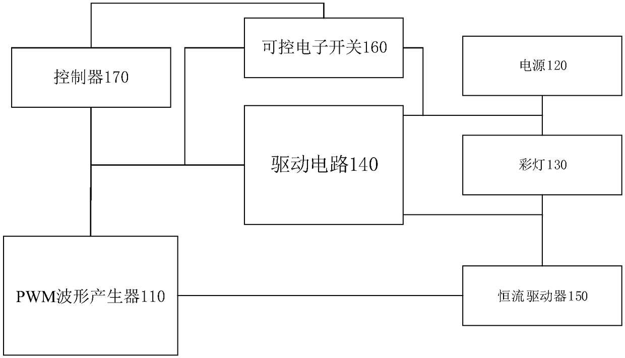
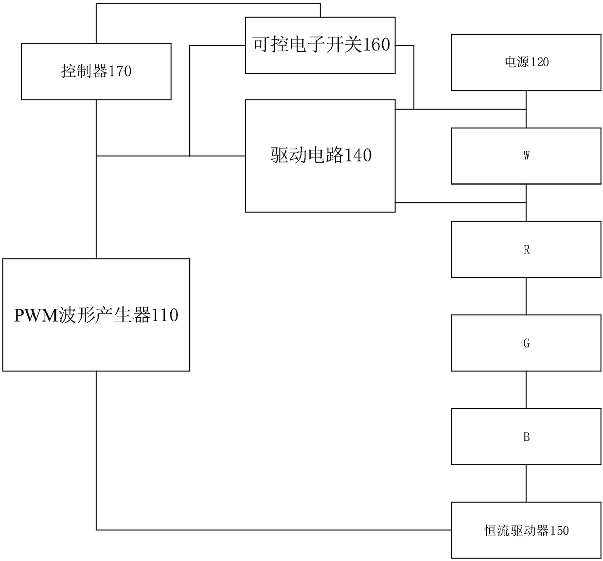
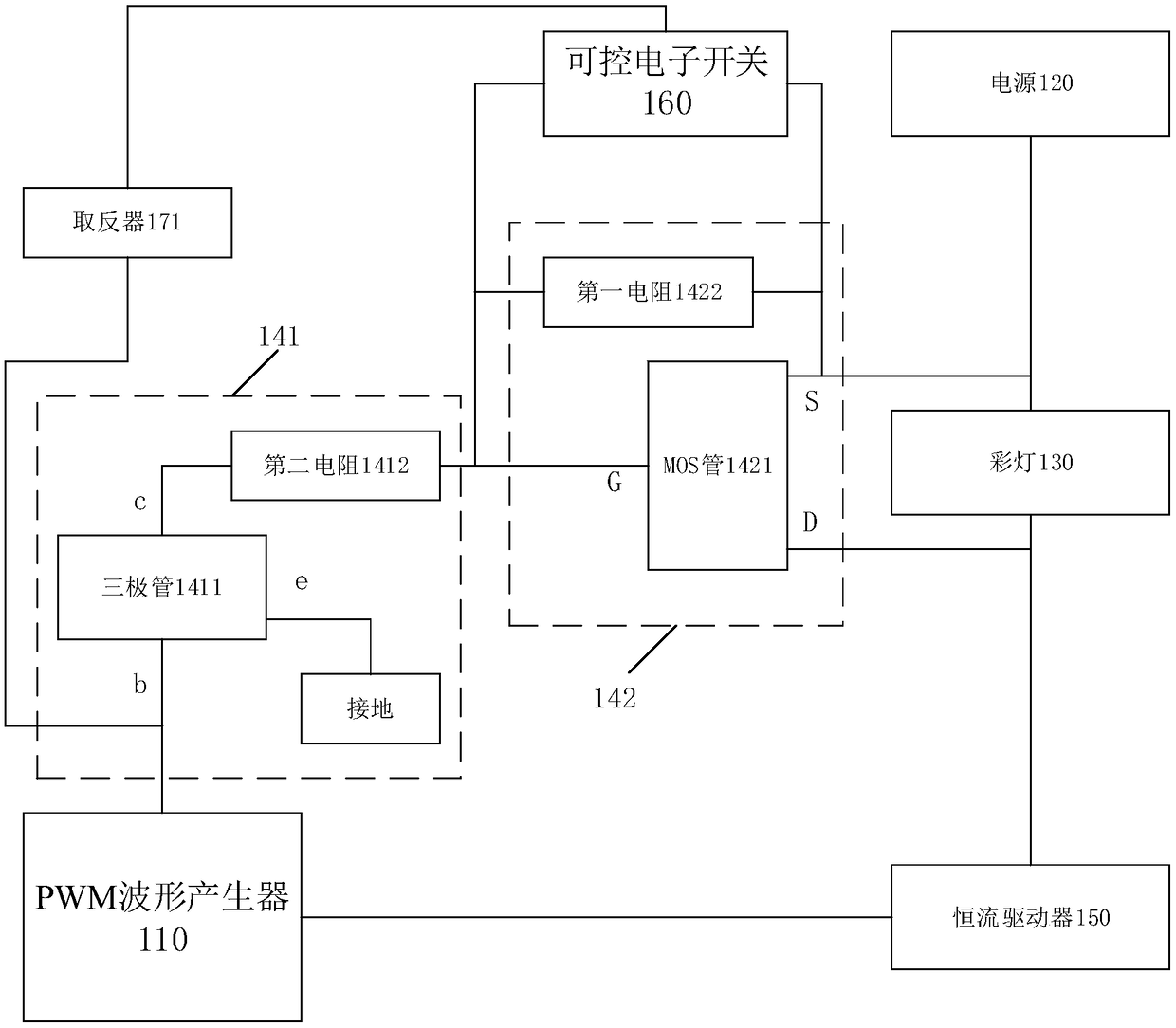
[0052] Please refer to figure 1 , figure 2 , image 3 , figure 1 It is a schematic diagram of the composition and structure of a colored light driving circuit provided by a specific embodiment of the present invention; figure 2 A structural schematic diagram of a WRGB light string of a colored light driving circuit provided by a specific embodiment of the present invention; image 3 It is a schematic diagram of an inverted structure of a colored light dr...


PUM


Abstract

The invention provides a color light lamp drive circuit and a drive method thereof. The drive circuit comprises a PWM waveform generator, a power supply, a colored lamp, a drive circuit, a constant current driver, a controllable electronic switch and a controller, wherein the power supply is serially connected with the colored lamp and the constant current driver; the PWM waveform generator is used for sending a first PWM drive waveform so as to drive the constant current driver to generate constant current; the output end of the drive circuit is connected to two ends of the colored lamp in parallel, the input end of the drive circuit is used for receiving a second PWM drive waveform generated by the PWM waveform generator and enabling the colored lamp to be short-circuited according to the second PWM drive waveform; the output end of the controllable electronic switch is connected to the output end and the input end of the drive circuit in parallel, and the input end of the controllable electronic switch is connected with the controller; and the controller is used for controlling the controllable electronic switch and enabling the input end and the output end of the drive circuitto be short-circuited when the drive circuit enables the colored lamp to be connected.

Description

technical field [0001] The invention relates to the technical field of electronic circuits, in particular to a colored light driving circuit and a driving method thereof. Background technique [0002] WRGB (White Red Green Blue, White Red Green Blue) technology A pixel is composed of W, R, G, B four pixels. The color is adjusted by individually driving the four pixels to emit light or not. At present, there are W, R, G, B dimming methods, one of which is to use 4-way drive circuits, which may be PMOS (positive channel Metal Oxide Semiconductor, P-type field effect tube) connected in parallel with W, R, G, and B lamp beads respectively. , by controlling the switch or shutdown of the 4-way drive circuit to realize the lighting of W, R, G, and B lamps respectively, so as to realize color adjustment, temperature adjustment, and brightness adjustment. [0003] However, this method has a defect, that is, when the dimming PWM (Pulse Width Modulation, pulse width modulation) frequ...

Claims


Application Information

Patent Timeline
IPC IPC(8): H05B37/02
CPCH05B47/10Y02B20/40
Inventor 孙胜利姜兆宁刘达平
Owner QINGDAO YEELINK INFORMATION TECH
Learn More