

Silicon controlled rectifier light modulation Bleeder circuit
A dimming control circuit and silicon dimming technology, applied in the field of LED dimming, can solve the problems of poor compatibility, poor dimming performance of thyristor, insufficient dimming depth, etc.
- Summary
- Abstract
- Description
- Claims
- Application Information
AI Technical Summary
Problems solved by technology
Method used
Image

Examples
Embodiment
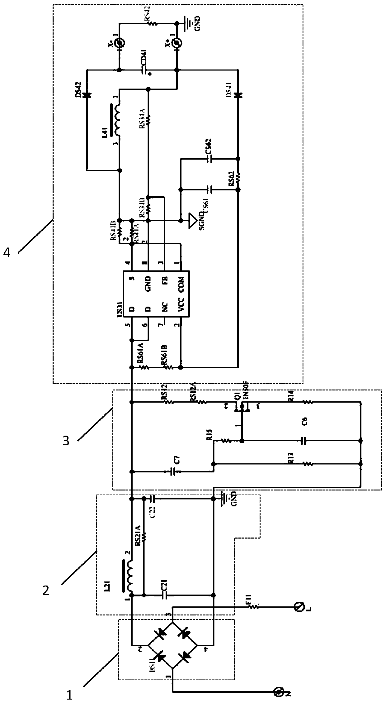
[0024] Example: such as figure 1 As shown, a schematic diagram of a thyristor dimming Bleeder circuit 3 is composed of a rectifier circuit 1, a filter circuit 2, a Bleeder circuit 3 and a dimming control circuit 4. The dimming control circuit 4 is composed of a driver U31 and a driver U31 respectively. The peripheral control circuit is composed of pins connected electrically. The driver U31 is MP4088LED driver. The MP4088LED driver has fast start-up speed, low delay, and the power derating at high temperature makes the system flicker-free when the ambient temperature is high. The input end of the rectification circuit 1 is electrically connected to the power supply, the output end of the rectification circuit 1 is electrically connected to the input end of the recording and broadcasting circuit, the output end of the filter circuit 2 is electrically connected to the input end of the Bleeder circuit 3, and the output end of the Bleeder circuit 3 is electrically connected to the ...
PUM
 Abstract
Description
Claims
Application Information