
Dimming control method, dimming control circuit and power converter using same

A dimming control circuit and power converter technology, applied in the field of dimming control circuits and power converters, can solve the problems of limited dimming depth, small dimming signal setting value, dimming dead zone, etc., and achieve widening and dimming The effect of increasing the light range, improving the dimming depth, and improving the current accuracy

Active Publication Date: 2022-01-07
SILERGY SEMICON TECH (HANGZHOU) CO LTD
View PDF12 Cites 0 Cited by
  • Summary
  • Abstract
  • Description
  • Claims
  • Application Information

AI Technical Summary

Problems solved by technology

[0003] However, in this LED load lighting system, when the setting value of the dimming signal is small, that is, when the dimming depth is deep, the power converter dims the LED load, and the output current no longer changes with the dimming signal, usually It is called "dimming dead zone". At the same time, the power stage circuit may not be able to provide enough energy to the LED load in time, resulting in poor output current accuracy and problems such as light flickering.
Therefore, in low-dimming applications, due to the small setting value of the dimming signal, the dimming depth is deep, and the current error accumulates, thus limiting the dimming depth

Method used


Image

  • Dimming control method, dimming control circuit and power converter using same
  • Dimming control method, dimming control circuit and power converter using same
  • Dimming control method, dimming control circuit and power converter using same

Examples


Embodiment Construction

[0058] The present invention is described below based on examples, but the present invention is not limited to these examples. In the following detailed description of the invention, some specific details are set forth in detail. The present invention can be fully understood by those skilled in the art without the description of these detailed parts. In order not to obscure the essence of the present invention, well-known methods, procedures, procedures, components and circuits have not been described in detail.

[0059] Additionally, those of ordinary skill in the art will appreciate that the drawings provided herein are for illustrative purposes and are not necessarily drawn to scale.

[0060] Meanwhile, it should be understood that in the following description, "circuit" refers to a conductive loop formed by at least one element or sub-circuit through electrical connection or electromagnetic connection. When an element or circuit is said to be "connected to" another eleme...


PUM


Abstract

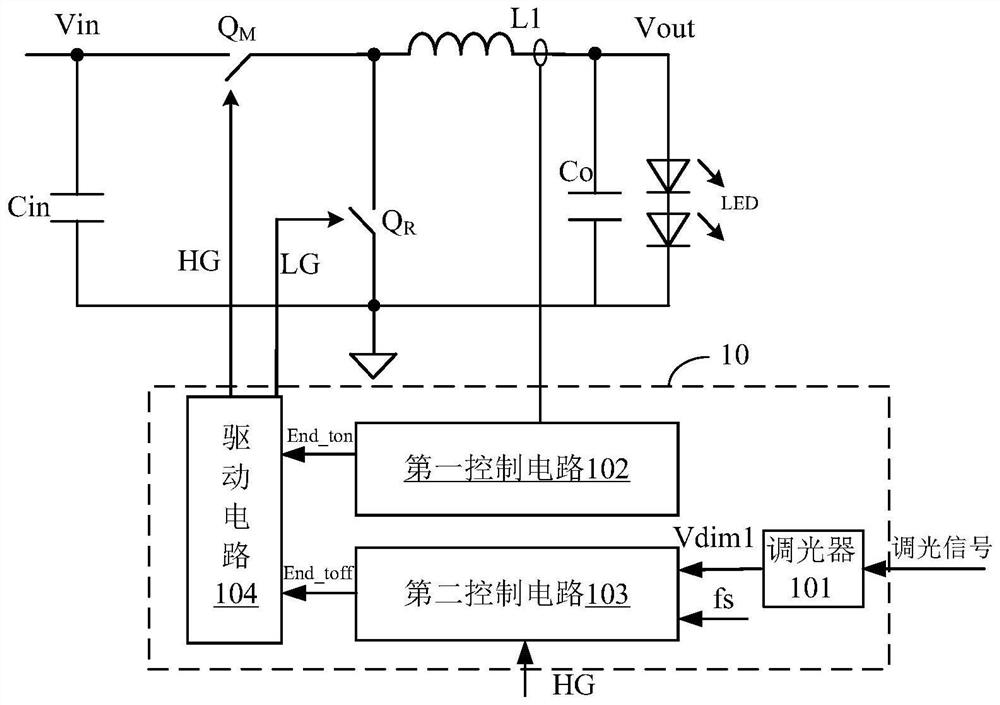
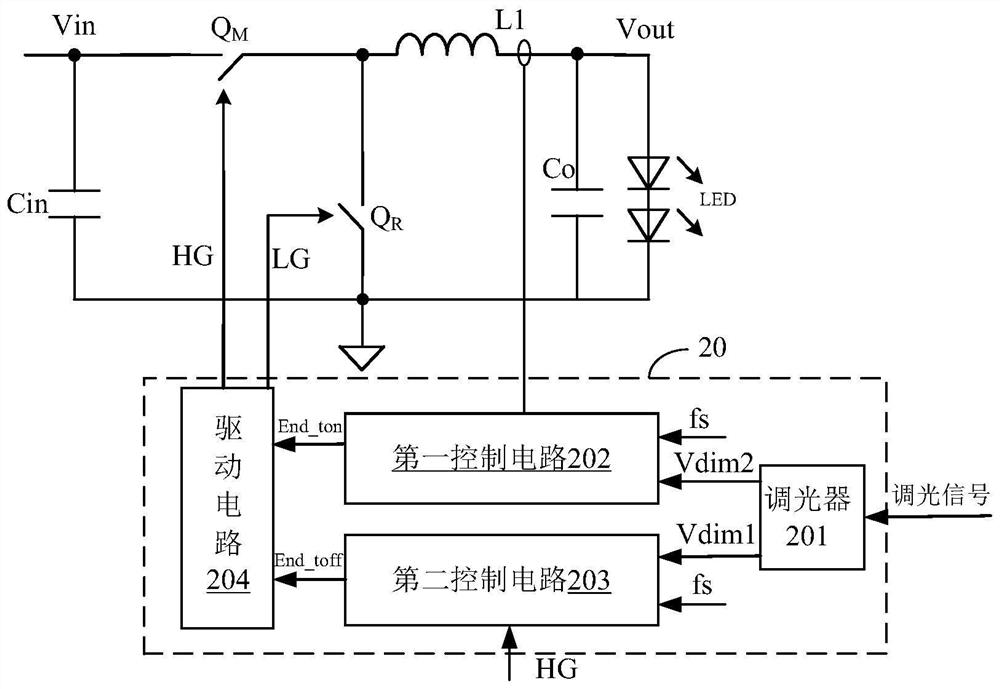
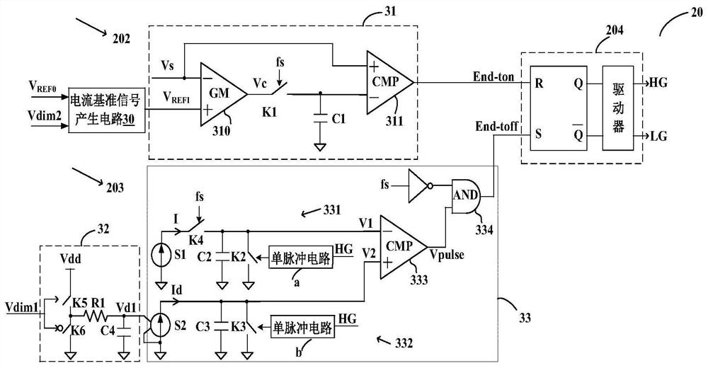
The application discloses a dimming control method, a dimming control circuit and a power converter applying the dimming control method. The technical solution of the embodiment of the present invention adjusts the length of the switching cycle of the power converter through the dimming signal, and at the same time controls the switching state of the power switch of the power stage circuit according to the output signal of the power stage converter, or controls the switching state of the power switch according to the dimming signal On-off state avoids the problem of poor output current accuracy due to the limited response time of the internal amplifier of the circuit system and the nonlinear relationship between the current reference signal and the dimming signal when the dimming signal setting value is small, and improves the current accuracy , while achieving combined dimming to increase dimming depth and widen the dimming range.

Description

technical field [0001] The present invention relates to power electronics technology, in particular to LED lighting technology, and more specifically, to a dimming control circuit, a dimming control method and a power converter. Background technique [0002] In lighting applications, LED loads are widely used due to their low power consumption and fast strobe speed. In the existing LED load lighting system, the power converter controls the power stage circuit to provide output current to the LED load through pulse width modulation to light the LED load. At the same time, the power converter adjusts the brightness of the LED load according to the set value of the dimming signal (for example, the duty cycle), thereby realizing dimming. [0003] However, in this LED load lighting system, when the setting value of the dimming signal is small, that is, when the dimming depth is deep, the power converter dims the LED load, and the output current no longer changes with the dimming...

Claims


Application Information

Patent Timeline
Patent Type & Authority Patents(China)
IPC IPC(8): H05B45/10H05B45/325H05B44/00
CPCH05B45/3725H05B45/14H05B45/10H05B45/325
Inventor 赖洪斌王建新
Owner SILERGY SEMICON TECH (HANGZHOU) CO LTD
Learn More