LED drive circuit and method

An LED drive and circuit technology, applied in electrical components, energy-saving control technology, etc., can solve the problems of low output current accuracy, high cost, large output current and output current ripple, etc., to reduce system cost, high precision, Reduce the effect of external pins and components

Active Publication Date: 2021-03-09
CRM ICBG (WUXI) CO LTD
View PDF5 Cites 3 Cited by
  • Summary
  • Abstract
  • Description
  • Claims
  • Application Information

AI Technical Summary

Problems solved by technology

[0006] In view of the shortcomings of the prior art described above, the purpose of the present invention is to provide an LED drive circuit and method for solving the problem of the large influence of peripheral components on the output current and output current ripple in the LED drive circuit in the prior art, and the output Problems such as low current accuracy and high cost

Method used


Image

  • LED drive circuit and method
  • LED drive circuit and method
  • LED drive circuit and method

Examples


Embodiment 1

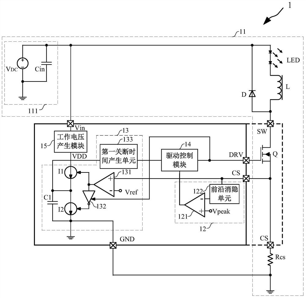
[0061] Such as image 3 As shown, this embodiment provides an LED driving circuit 1, and the LED driving circuit 1 includes:

[0062] Buck module 11, peak value control module 12, off-time control module 13 and drive control module 14.

[0063] Such as image 3 As shown, the step-down module 11 performs step-down processing on the input voltage to provide electric energy for the LED lamp segment.

[0064] Specifically, in this embodiment, the step-down module 11 includes a power input unit 111 , an LED segment LED, an inductor L, a diode D, a power switch tube Q and a sampling unit.

[0065] More specifically, in this embodiment, the power input unit 111 includes a DC power supply V DC and input capacitance Cin, the DC power supply V DC Obtained by methods including but not limited to AC power rectification. The power input unit 111 only needs to provide a DC input voltage, and the implementation is not limited to this embodiment, which will not be repeated here.

[0066...

Embodiment 2

[0097] Such as Figure 5 As shown, this embodiment provides an LED driving circuit, and the difference from Embodiment 1 lies in that the implementation of the off-time control module 13 is different.

[0098] Specifically, the off-time control module 13 includes a transconductance amplifier 134, a first switch S1, a second switch S2, a third switch S3, a first resistor R1, a second resistor R2, a second capacitor C2 and a second switch Off time generation unit 135.

[0099] More specifically, one end of the first switch S1 is connected to the sampling voltage Vcs, and the other end is connected to the non-inverting input terminal of the transconductance amplifier 134, and the non-inverting input terminal of the transconductance amplifier 134 is connected via the first The resistor R1 is grounded; one end of the second switch S2 is connected to the reference voltage Vref, and the other end is connected to the inverting input terminal of the transconductance amplifier 134, and...


PUM


Abstract

The invention provides an LED drive circuit and method. The LED drive circuit comprises: a voltage reduction module; a peak value control module which is used for outputting a turn-off control signalwhen the current flowing through the LED lamp section reaches a set peak value; a turn-off time control module which is used for adjusting the turn-off time of the power switch tube; and a driving control module which is used for generating a driving signal based on output signals of the peak value control module and the turn-off time control module. The power switch tube is controlled by adoptingfixed peak turn-off; and when the output current is small, the turn-off time is shortened, and when the output current is large, the turn-off time is prolonged, and the turn-off time of the power switch tube is self-adaptively adjustable. Fixed peak current turn-off is adopted, overshoot is avoided during output in loop control, and rapid starting can be achieved; after average current detection,the output current precision is high, the turn-off time is adjusted internally, external setting is not needed, external pins and elements can be reduced, and the system cost is reduced; and LED ripple current is internally fixed and is not influenced by external conditions and element parameters.

Description

technical field [0001] The invention relates to the field of LED driving, in particular to an LED driving circuit and method. Background technique [0002] In the DC-DC high-power LED constant current drive scheme, a step-down circuit (Buck) is usually used, such as figure 1 As shown, the current detection resistor R1' is directly connected in series with the LED, which can accurately detect and control the output current. Because the switch SW is at the high-end bus voltage, it is usually necessary to use a PMOS device, but once the input voltage Vin is relatively high, the choice of PMOS is relatively small, and the cost is relatively high; if an NMOS device is used, the step-down control module needs to be a high voltage For the driver, the chip needs to adopt a high-voltage process, and the cost will increase. [0003] The LED can be placed on the high-end output, and the switch SW can be placed on the ground terminal for control. The switch SW uses an NMOS device, and...

Claims


Application Information

Patent Timeline
Patent Type & Authority Applications(China)
IPC IPC(8): H05B45/345
CPCY02B20/40
Inventor 刘军李亮卢圣晟吴泉清
Owner CRM ICBG (WUXI) CO LTD
Why Eureka
Try Eureka