Current detecting circuit

a current detection and circuit technology, applied in the direction of circuit inspection/indentification, instruments, measurement using digital techniques, etc., can solve problems such as difficulty in detecting accurate currents, and achieve the effect of improving current accuracy

Inactive Publication Date: 2016-12-08
SAMSUNG SDI CO LTD
View PDF10 Cites 4 Cited by
  • Summary
  • Abstract
  • Description
  • Claims
  • Application Information

AI Technical Summary

Benefits of technology

[0028]According to aspects of some embodiments of the present invention, it may be possible to provide a current detecting circuit with improved current accuracy.

Problems solved by technology

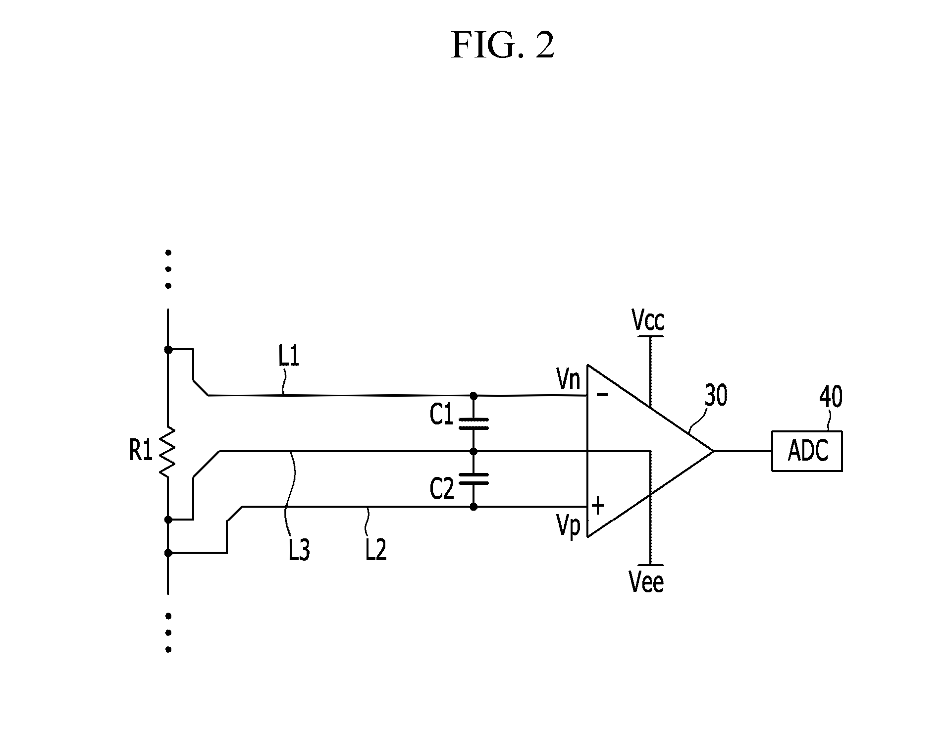
Accordingly, a common mode current according to a potential difference flows, and it is difficult to detect an accurate current due to a noise component carried on the common mode current.

Method used


Image

  • Current detecting circuit
  • Current detecting circuit
  • Current detecting circuit

Examples


Embodiment Construction

[0033]Aspects of embodiments of the present invention will be described more fully hereinafter with reference to the accompanying drawings, in which example embodiments of the invention are shown. As those skilled in the art would realize, the described embodiments may be modified in various different ways, all without departing from the spirit or scope of the present invention.

[0034]In the drawings, the thickness of layers, films, panels, regions, etc., are exaggerated for clarity. Like reference numerals designate like elements throughout the specification. It will be understood that when an element such as a layer, film, region, or substrate is referred to as being “on” another element, it can be directly on the other element or intervening elements may also be present. In contrast, when an element is referred to as being “directly on” another element, there are no intervening elements present.

[0035]It will be understood that, although the terms “first,”“second,”“third,” etc., ma...


PUM


Abstract

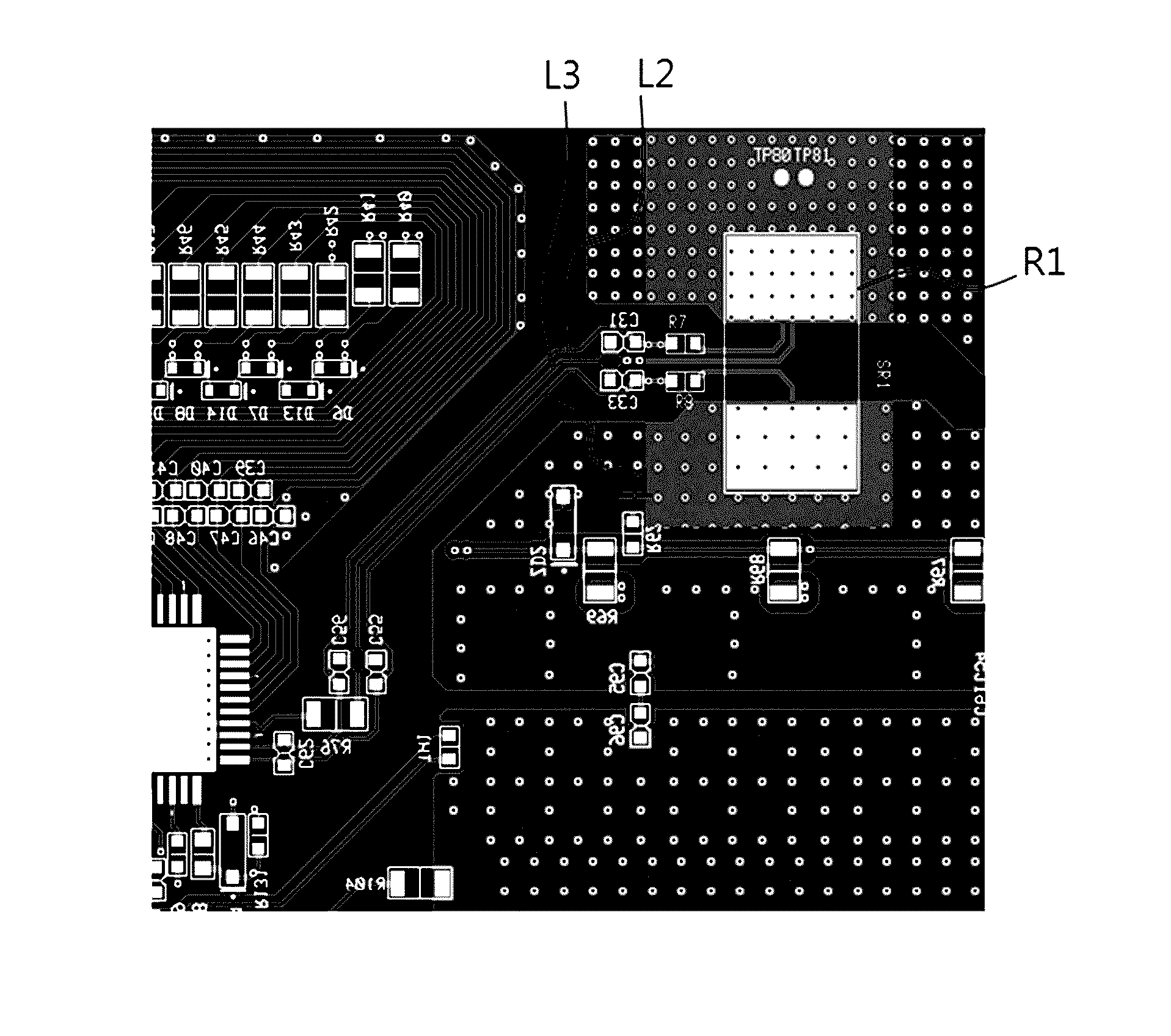
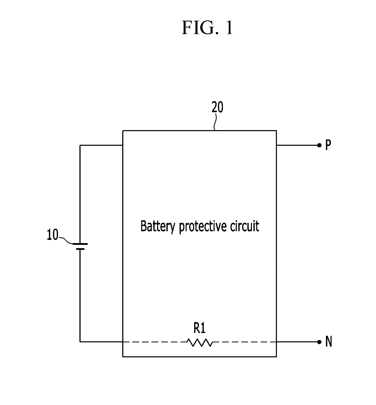
A current detecting circuit includes: a shunt resistor; an amplifier; a first signal line connecting a first terminal of the shunt resistor to a first input terminal of the amplifier; a second signal line connecting a second terminal of the shunt resistor to a second input terminal of the amplifier; and a third signal line connecting the second terminal of the shunt resistor to a first power supply terminal of the amplifier.

Description

CROSS-REFERENCE TO RELATED APPLICATION[0001]This application claims priority to and the benefit of Korean Patent Application No. 10-2015-0080860, filed in the Korean Intellectual Property Office on Jun. 8, 2015, the entire content of which is incorporated herein by reference.BACKGROUND[0002]1. Field[0003]Aspects of embodiments of the present invention relate to a current detecting circuit.[0004]2. Description of the Related Art[0005]A shunt resistor may be arranged on a predetermined current path to measure a current according to a voltage by amplifying both voltages.[0006]For example, in order to measure a minute current difference, a resistance value of the shunt resistor may be precisely manufactured. The resistance value of the shunt resistor is generally very low, and as a result, easily influenced by a resistance value generated according to a pattern of a connected wire. Therefore, how to design the pattern of the wire is an important consideration for designers.[0007]Further...

Claims


Application Information

Patent Timeline
Patent Type & Authority Applications(United States)
IPC IPC(8): G01R19/00G01R17/02
CPCG01R19/0092G01R17/02G01R19/25G01R15/146H02H7/18H03F3/45928H03F1/26H03F3/45475H03F2200/462H03F2203/45548H05K1/0268G01R1/203G01R31/382
Inventor BAE, JEONGGUKK.V., SUNDARAAMAN
Owner SAMSUNG SDI CO LTD
Why Eureka
Try Eureka