Constant current source circuit and sampling circuit

A technology of sampling circuit and constant current source, which is applied in the direction of light source, electric light source, electrical components, etc., can solve the problems of high power loss and loss, and achieve the effect of increasing power, reducing power consumption and high efficiency

Active Publication Date: 2013-04-17
LEDVANCE GMBH
View PDF7 Cites 4 Cited by
  • Summary
  • Abstract
  • Description
  • Claims
  • Application Information

AI Technical Summary

Problems solved by technology

The main disadvantage of this prior art is that the current sampling voltage is as high as 2.495V resulting in large losses
[0005] In the above two schemes, the voltage across the sampling resistor is close to the forward voltage drop VF (usually 0.7-3.1V) when the light-emitting diode as the load is turned on, so a large power loss is caused

Method used


Image

  • Constant current source circuit and sampling circuit
  • Constant current source circuit and sampling circuit
  • Constant current source circuit and sampling circuit

Examples


Embodiment Construction

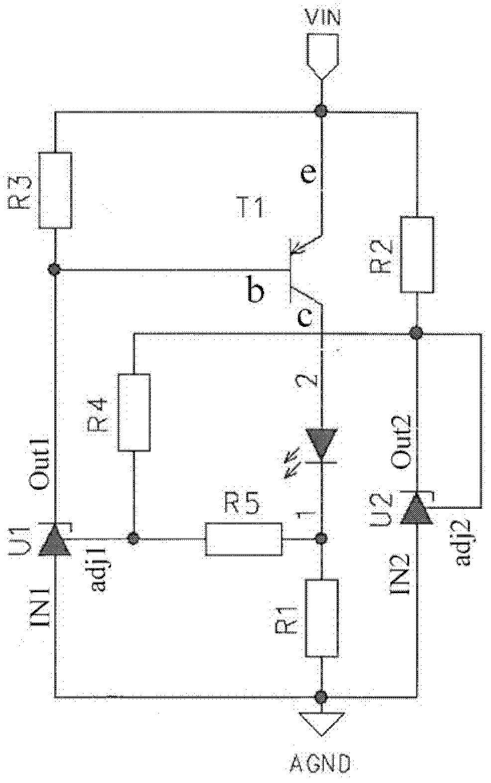
[0026] image 3 A specific embodiment of the constant current source circuit according to the present invention is shown. Such as image 3 As shown, the constant current source circuit includes: a main circuit including a transistor T1, a plurality of light-emitting diodes connected in series as a load, a first three-terminal voltage regulator U1, a sampling resistor R1, and a third resistor R3; An adjustment unit of the second three-terminal voltage regulator U2, the second resistor R2, the fourth resistor R4, and the fifth resistor R5 of the voltage stabilizing unit.

[0027] The output terminal Out1 of the first regulator U1 is connected to the voltage input terminal VIN through the third resistor R3, and the third resistor R3 is connected between the base b of the transistor T1 and the voltage input terminal VIN. The emitter e of the transistor T1 is connected to the voltage input terminal VIN, and the collector c of the transistor T1 is connected to the anode terminals ...


PUM


Abstract

The invention relates to a constant current source circuit which comprises a main circuit. The main circuit comprises a first three-end stabilizer, a transistor, a sampling resistor and a load, wherein an output end of the first three-end stabilizer is connected with a control electrode of the transistor, a reference electrode of the transistor is connected with a voltage input end, a working electrode is connected with one end of the load, the other end of the load is connected with one end of the sampling resistor, and the other end of the sampling resistor and an input end of the first three-end stabilizer are respectively connected with a reference potential. The constant current source circuit is characterized by further comprising an adjusting unit which comprises a voltage stabilizing unit, a fourth resistor and a fifth resistor. The voltage stabilizing unit generates second reference voltage larger than first reference voltage generated by the first three-end stabilizer and provides the second reference voltage to an adjusting end of the first three-end stabilizer through the fourth resistor, and the fifth resistor is connected between a node between the load and the sampling resistor and the adjusting end of the first three-end stabilizer. The constant current source circuit has the advantages of being high in efficiency, high in current accuracy and good in temperature excursion performance. The invention further relates to a sampling circuit.

Description

technical field [0001] The invention relates to a constant current source circuit and a sampling circuit. Background technique [0002] At present, the constant current source circuit has been widely used in circuits with high requirements for current stability. [0003] In the prior art (see attached figure 1 ) proposed to use a transistor T2 to realize the constant current function. Because the VBE of the transistor T2 is 0.7V, the sampling voltage through the resistor R1 is about 0.6V. The final stable current: I=VBE / R1. The main disadvantage of this circuit is poor current accuracy and high temperature drift. The reason is that the transistor has a large VBE range (0.58-0.75V) and has a high temperature drift. [0004] prior art (see attached figure 2 ) Use a three-terminal shunt regulator U1 to realize the constant current source circuit. Such as figure 2 As shown, the constant current source circuit includes a three-terminal shunt regulator U1 and a transisto...

Claims


Application Information

Patent Timeline
Patent Type & Authority Applications(China)
IPC IPC(8): G05F1/625H05B44/00
CPCG05F3/20H05B45/395Y02B20/30H05B45/3725H02M3/155
Inventor 蒋春军张德召米德尔·特加科戴雪维
Owner LEDVANCE GMBH
Why Eureka
Try Eureka