Microfluidic droplet generation chip

A droplet generation and microfluidic technology, applied in the field of digital PCR, can solve problems such as sample loss, and achieve the effects of convenient operation, obvious advantages, and small flow rate ratio relationship.

Active Publication Date: 2021-01-26
SHENZHEN BIORAIN BIOTECHNOLOGY CO LTD
View PDF5 Cites 0 Cited by
  • Summary
  • Abstract
  • Description
  • Claims
  • Application Information

AI Technical Summary

Problems solved by technology

Generation of droplets in this manner results in a partial loss of the sample before reaching equilibrium

Method used


Image

  • Microfluidic droplet generation chip
  • Microfluidic droplet generation chip
  • Microfluidic droplet generation chip

Examples


Embodiment Construction

[0024] The following will clearly and completely describe the technical solutions in the embodiments of the present invention with reference to the accompanying drawings in the embodiments of the present invention. Obviously, the described embodiments are only some, not all, embodiments of the present invention. Based on the embodiments of the present invention, all other embodiments obtained by persons of ordinary skill in the art without creative efforts fall within the protection scope of the present invention.

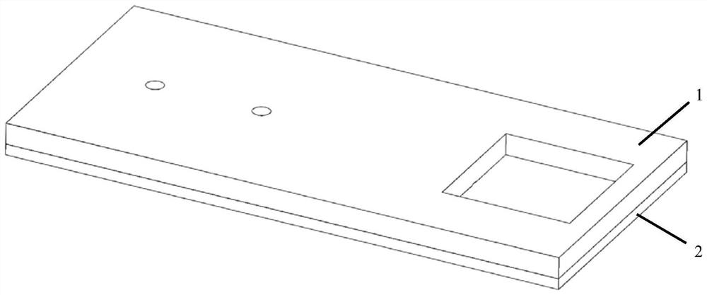
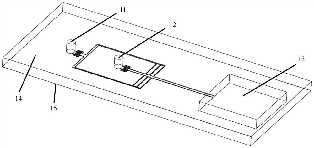
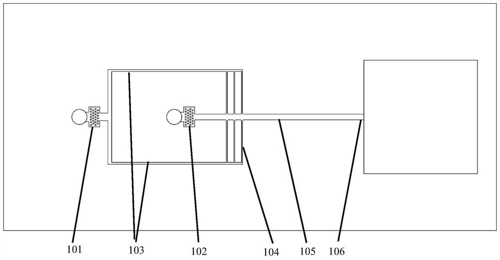
[0025] Figure 1-Figure 5 It is the first embodiment of the microfluidic droplet generation chip provided by the present invention, which is used to generate droplets with more reliable size and stability of the sample phase (water) wrapped by the continuous phase (oil). The microfluidic droplet generation chip includes a chip body 1, a sealing layer 2, a sample phase injection hole 11 and a continuous phase injection hole 12 that run through the upper and lower su...


PUM

PropertyMeasurementUnit
widthaaaaaaaaaa
depthaaaaaaaaaa
widthaaaaaaaaaa

Abstract

The invention discloses a microfluidic droplet generation chip, the microfluidic droplet generation chip includes a chip body, a sealing layer, a sample phase injection hole and a continuous phase injection hole penetrating through the upper and lower surfaces of the chip body, and a droplet A storage pool, and a continuous phase channel, a sample phase channel, a sample phase branch channel, a continuous phase filter area, and a sample phase filter area arranged on the lower surface of the chip body.

Description

technical field [0001] The invention relates to the technical field of digital PCR, in particular to a microfluidic droplet generating chip. Background technique [0002] At present, the methods for preparing droplets based on microfluidics mainly include T-channel method and fluid focusing method. The T-shaped channel method utilizes the geometric characteristics of the intersection of two microchannels to generate droplets due to the momentum change caused by the shear force of the continuous phase when the front of the continuous phase liquid turns at the intersection. The flow focusing method is to make the continuous phase fluid "squeeze" the front of the continuous phase liquid from both sides of the intersection, and use the "neck" chip of the channel downstream of the liquid front to shrink and deform the front of the dispersed liquid and destabilize it, thereby Droplets are formed. The disadvantage of these two methods is that it is necessary to adjust the pressur...

Claims


Application Information

Patent Timeline
Patent Type & Authority Patents(China)
IPC IPC(8): B01L3/00
CPCB01L3/5027B01L3/502784
Inventor 於林芬阳巍
Owner SHENZHEN BIORAIN BIOTECHNOLOGY CO LTD
Why Eureka
Try Eureka