
Hydraulic braking system of railway vehicle

A rail vehicle, hydraulic braking technology, applied in railway braking system, operating mechanism of railway vehicle brakes, hydrostatic brakes, etc.

Active Publication Date: 2019-02-19
深圳市勇拓兴科技有限公司
View PDF7 Cites 0 Cited by
  • Summary
  • Abstract
  • Description
  • Claims
  • Application Information

AI Technical Summary

Problems solved by technology

[0003] The traditional horizontal normally open brake cannot realize the brake and brake display function, and the support block of the conventional pedal cannot be adjusted, so it cannot play the role of the brake. When the brake is required, the pusher is pushed up, and the brake locks the brake. When the brake needs to be locked for a long time after get off work, the pusher must work for a long time, which shortens the service life, wastes energy, and has potential safety hazards during use, which cannot meet the user's on-site use requirements

Method used


Image

  • Hydraulic braking system of railway vehicle
  • Hydraulic braking system of railway vehicle

Examples


Embodiment Construction

[0024] The purpose of the present invention can be achieved through the following technical solutions:

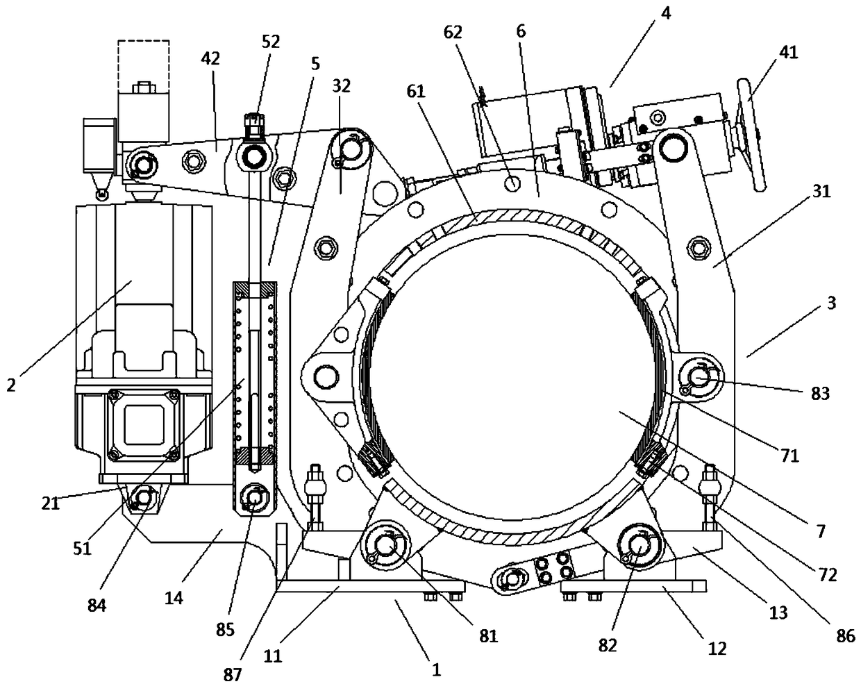
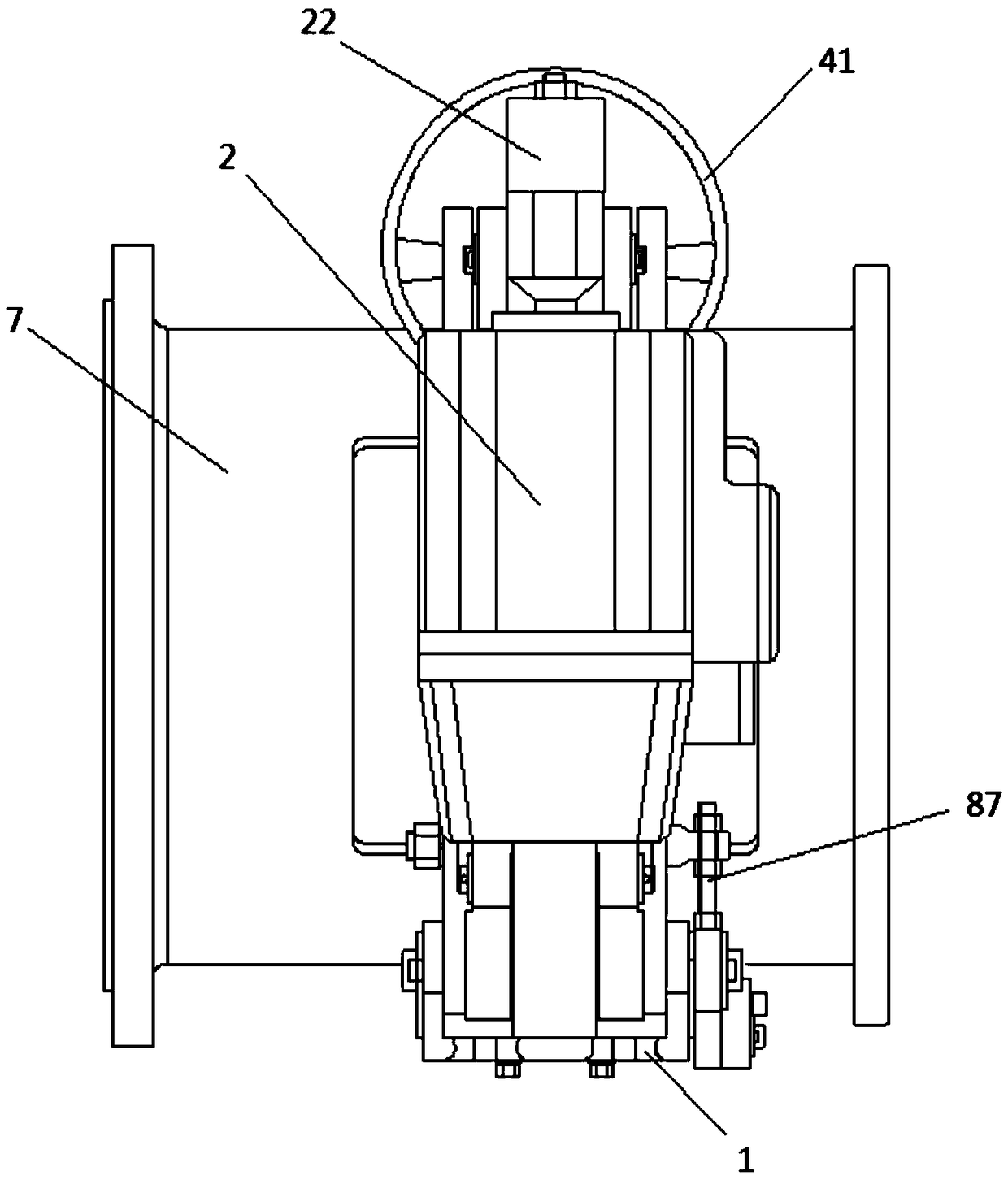
[0025] A hydraulic braking system for rail vehicles, see Figure 1-2 , including a brake frame 1, a frequency conversion pusher 2, a brake arm 3, a manual brake mechanism 4, a tie rod 5, a brake hub 6, and a brake mechanism 7;

[0026] The brake hub 6 is mounted on the outer bottom of the hub, and a brake mechanism 7 is installed on the inner side of the brake hub 6; a brake arm 3 is installed on the brake hub 6, and the top of the brake arm 3 is installed on the manual brake mechanism 4. The bottom end of the brake arm 3 is installed on the brake frame 1; the frequency conversion pusher 2 and the tie rod 5 are respectively installed between the brake frame 1 and the manual brake mechanism 4, and the two ends of the frequency conversion pusher 2 and the tie rod 5 are respectively Installed on the brake frame 1 and the manual brake mechanism 4;

[0027] Described brake fra...


PUM


Abstract

The invention discloses a hydraulic braking system of a railway vehicle. The system comprises a brake frame, a variable-frequency pusher, a brake arm, a manual brake mechanism, a tie rod, a brake huband a brake mechanism, wherein the brake hub is arranged at the bottom of the outer side of a hub, and the brake mechanism is installed on the inner side of the brake hub; the brake arm is installed on the brake hub, the top end of the brake arm is installed on the manual brake mechanism, and the bottom end of the brake arm is installed on the brake frame; the variable-frequency pusher and the tierod are arranged between the brake frame and the manual brake mechanism respectively; the two ends of the variable-frequency pusher and the two ends of the tie rod are arranged on the brake frame andthe manual brake mechanism respectively. The system has the advantages that the brake mechanism is installed, the angle does not need to be adjusted, long-time brake locking and power supply fault electric locking functions are added, detachment and installation are convenient, and abrasion compensation and abrasion limit faults of the brake mechanism are prompted.

Description

technical field [0001] The invention relates to a hydraulic braking system for a rail vehicle, in particular to a hydraulic braking system that has the functions of installing the braking mechanism without adjusting the angle, increasing the functions of long-term braking locking and power supply failure electric locking, convenient disassembly and installation, and wear-resistant braking mechanism. Compensation and wear limit fault codes for rail vehicle hydraulic brake systems. Background technique [0002] The slewing and running mechanisms of rail vehicles need braking and accurate alignment during operation. Since the running speed of rail vehicles is different each time, it is necessary for the operator to control the brakes to generate different braking forces according to different situations. [0003] The traditional horizontal normally open brake cannot realize the brake and brake display function, and the support block of the conventional pedal cannot be adjusted,...

Claims


Application Information

Patent Timeline
Patent Type & Authority Applications(China)
IPC IPC(8): B61H11/06B61H13/36B61H3/00
CPCB61H3/00B61H11/06B61H13/36
Inventor 费宏阳费金秀雷梦云
Owner 深圳市勇拓兴科技有限公司
Learn More