Novel down hole drilling rig dust exhaust rubber-coupled molding curing dust suppression system

A technology of down-the-hole drilling rigs and glue joints, which is applied in chemical instruments and methods, separation methods, construction, etc., can solve the problems of reduced dust removal efficiency, equipment and air pollution hazards, and disappearance, so as to prolong the life of equipment, reduce equipment pollution, reliable performance

Pending Publication Date: 2019-02-19
唐山冀东水泥股份有限公司唐山分公司 +1
View PDF0 Cites 2 Cited by
  • Summary
  • Abstract
  • Description
  • Claims
  • Application Information

AI Technical Summary

Problems solved by technology

However, the filter element is bound to be easily blocked by fine dust during the dust and air separation process, which increases the filter resistance of the filter element and reduces or even eliminates the dust removal efficiency.
At this time, back blowing must be carried out to clean the filter element to restore the filtering function. This process needs to release the dust suction pressure. During the process, there is intermittent dust in the air, which cannot meet the environmental protection requirements.
[0007] 2. At the same time, the dust collection box discharges dust to the ground. At the same time, due to the blowing action of the natural wind in dry weather on the discharged dust, it is inevitable that dust will pollute the air environment near the drilling rig, causing pollution hazards to equipment and air.
At present, the dust and slag discharge can only be temporarily piled in the open air, waiting to be mixed into the explosion pile to be fused as raw materials during blasting or waiting to be processed here

Method used


Image

  • Novel down hole drilling rig dust exhaust rubber-coupled molding curing dust suppression system
  • Novel down hole drilling rig dust exhaust rubber-coupled molding curing dust suppression system
  • Novel down hole drilling rig dust exhaust rubber-coupled molding curing dust suppression system

Examples


Embodiment Construction

[0030] Below in conjunction with accompanying drawing, the present invention will be further described.

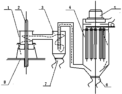
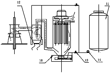
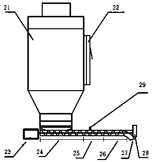
[0031] The technical scheme that this specific embodiment adopts is: see figure 2 As shown, it includes a dust collection cover 1, a settling chamber 3, a filter element dust collector 4, and a dust removal fan 5, and is characterized in that: the filter element dust collector 4 is provided with a dust collection box 21; on the side wall of the dust collection box 21 Equipped with back-blowing buffer filter chamber 22;

[0032] It also includes a forced-stirring adhesive dust removal mechanism 10 and an intelligent control dust-fixing mechanism; the forced-stirring rubber dust removal mechanism 10 is located at the tail of the filter element dust collector 4; the intelligent control dust-fixing mechanism is located in the settling chamber The dust outlet 7 of the filter element dust collector and the dust outlet 6 of the filter element dust collector; the forced stirring...


PUM


Abstract

The invention discloses a novel down hole drilling rig dust exhaust rubber-coupled molding curing dust suppression system. The novel down hole drilling rig dust exhaust rubber-coupled molding curing dust suppression system comprises a dust catching cover, a settling chamber, a filter core dust collector and a dust removal fan, and a dust collecting box is arranged on the filter core dust collector; a backblow buffer filter chamber is arranged on the side wall of the dust collecting box; the novel down hole drilling rig dust exhaust rubber-coupled molding curing dust suppression system furthercomprises a forced mixing rubber-coupled dust exhaust mechanism and an intelligent control dust-fixing mechanism; the forced mixing rubber-coupled dust exhaust mechanism and the intelligent control dust-fixing mechanism are all connected with a controller; a mixing rubber-coupled moulding system is designed on the tail part of a fine dust collector dust exhaust system, the separated fine dust is subjected to wetting, stirring and cross-linking to form granular to be discharged, and an effectively eliminate drilling rig operates in the process of backblowing and regeneration of a filter core for dust leakage; and meanwhile, an electronic control automatic quantitative dust suppressant spraying device is designed on the upper part of a dust exhaust stack and on the upper part of a cyclone slag collecting and discharging cover, the dust discharge stack is subjected to surface layer gluing connection curing treatment to control the possibility of dust and slag discharge being temporarily stacked in stope under the influence of natural wind before blasting, and a secondary dust source is eliminated.

Description

technical field [0001] The invention relates to a dust suppression device, in particular to a novel dust suppression system for down-the-hole drilling rigs which are dust-expelled and cemented. Background technique [0002] At present, the dust removal method of the dust removal system of the down-the-hole drilling rig used in open pit mines mostly adopts a dry filter element and a gravity natural fall dust removal system. The existing dry dust removal system is mainly composed of a dust collection cover 1, a settling chamber 3, a filter element dust collector 4, and a dust removal fan 5, such as figure 1 shown. [0003] When the drilling rig drills a hole on the rock surface 8, the compressed air of the air compressor is blown into the borehole by the drill rod 2, and the dust residue in the hole is blown out. The dust removal fan 5 is started, and a negative pressure is formed in the dust collection cover 1 of the dust removal system, and the dust residue enters the dus...

Claims


Application Information

Patent Timeline
Patent Type & Authority Applications(China)
IPC IPC(8): E21B21/015E21B21/16B01D50/00
CPCE21B21/015E21B21/16B01D50/20
Inventor 孙海涛洪宇周凯轩纪福成张文玉马劲松王程远宋利明孙文豪
Owner 唐山冀东水泥股份有限公司唐山分公司
Why Eureka
Try Eureka