Supercharge Your Innovation With Domain-Expert AI Agents!

A Condenser Tube Layout Method with Low Condensation Resistance of Exhaust Steam

A condenser and resistance technology, applied in steam/steam condensers, lighting and heating equipment, etc., can solve the problems of insufficient use of steam to diffuse steam and low condensing pressure.

Active Publication Date: 2020-07-07
董若言
View PDF2 Cites 0 Cited by
  • Summary
  • Abstract
  • Description
  • Claims
  • Application Information

AI Technical Summary

Problems solved by technology

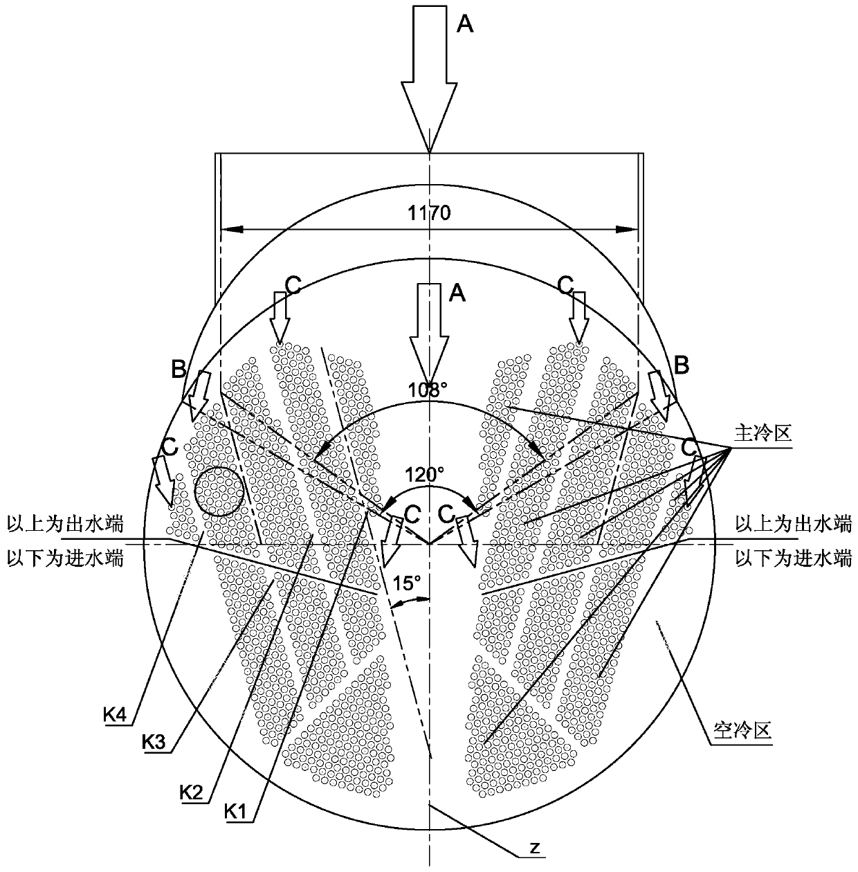
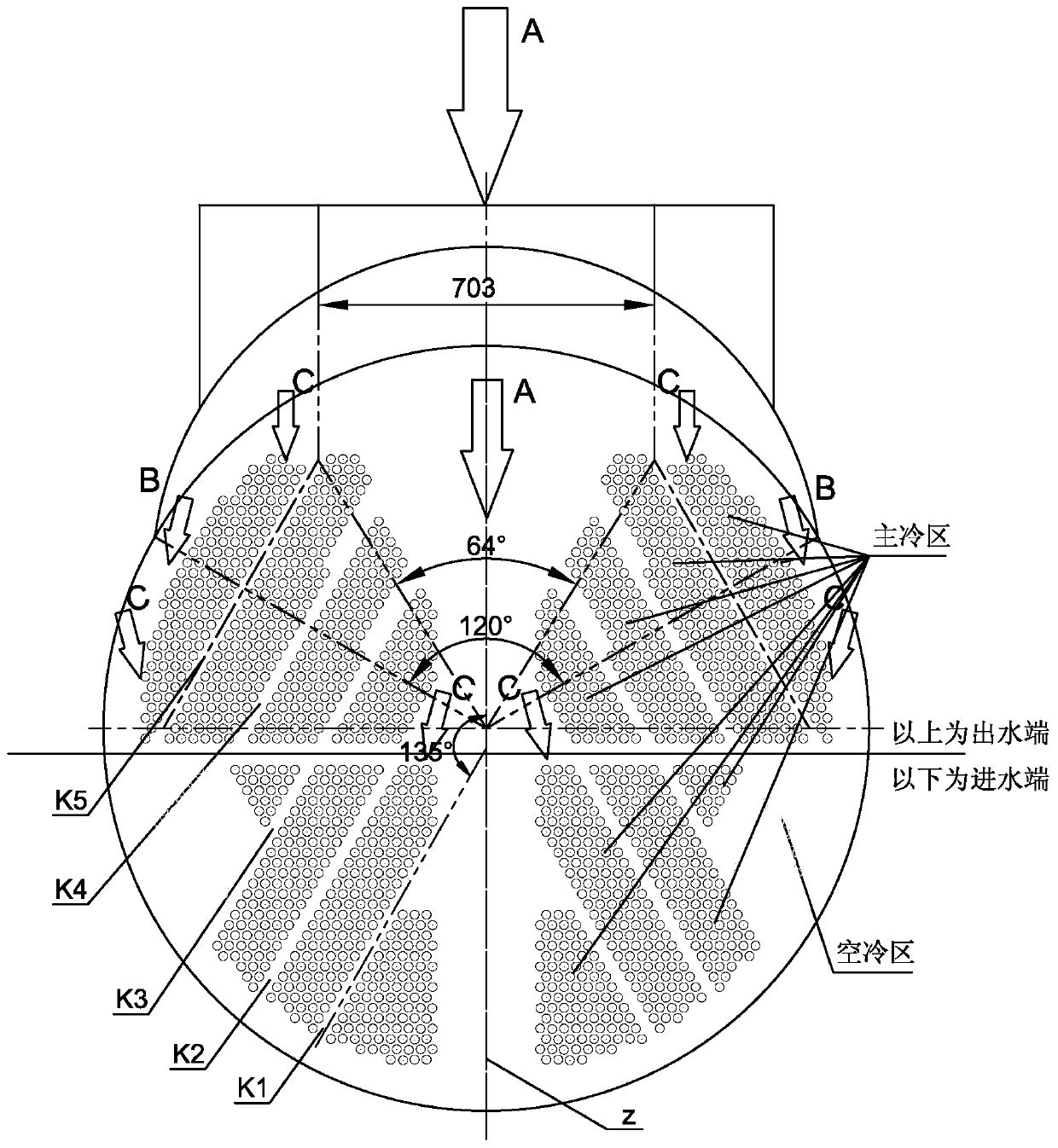
And when the exhaust steam enters the tube bundle and condenses, the volume rapidly decreases to produce a downward and centripetal vacuum suction (for the tube bundle with two flows separated by the diaphragm of the water chamber, the steam flows from the warm end (upper part) of the water outlet end to the water inlet end) The cold end (lower part) condenses, the lower the cooling water temperature is, the lower the condensing pressure is, and the running direction of the condensing airflow is as follows: figure 1 , figure 2 As shown by the arrow C in the figure; for a single-flow tube bundle, the steam is also condensed from the upper part of the tube bundle (the near end of the steam) to the lower part (the far end of the steam), such as figure 1 , figure 2 As shown by the arrow C in the middle), it is not consistent with the diffusion groove that guides the flow outward and downward at 135°, so the suction force of the steam phase change cannot be fully utilized to diffuse the steam

Method used


Image

  • A Condenser Tube Layout Method with Low Condensation Resistance of Exhaust Steam
  • A Condenser Tube Layout Method with Low Condensation Resistance of Exhaust Steam
  • A Condenser Tube Layout Method with Low Condensation Resistance of Exhaust Steam

Examples


Embodiment Construction

[0024] The present invention will be further described below in conjunction with the accompanying drawings and through implementation examples.

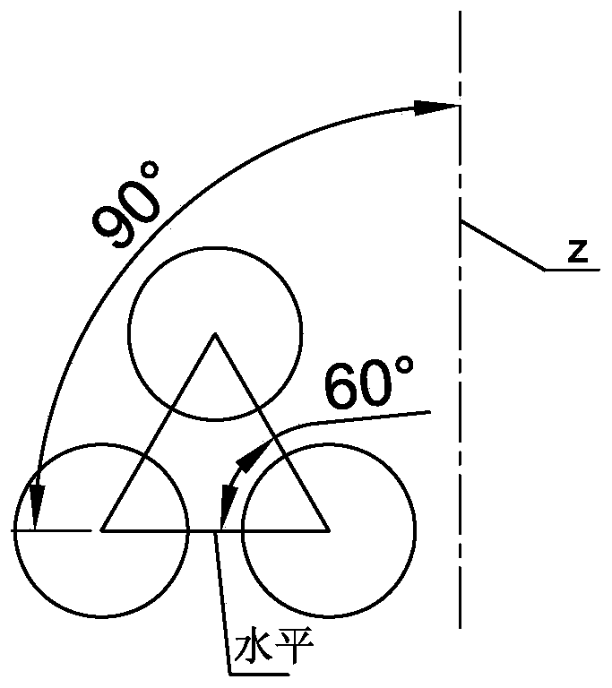
[0025] The pipe layout of the existing condenser (see figure 2 ), including 1656 tubes in the main cooling zone (i.e. heat exchange tubes) and 180 tubes in the air cooling zone, a total of 1836 tubes (these tubes form several tube bundles), as well as the water chamber diaphragm channel and the necessary diffusion tank, arranged in diameter In the tube sheet of 1.6 meters; the two ends of all the tubes are respectively fixed on the tube sheets at both ends of the condenser, and the steam inlet of the condenser is located at the top of the condenser. The tube bundles are distributed in a band shape with a bandwidth of 6 rows, and the adjacent tubes are arranged in an equilateral triangle ( image 3 shown), five diffusion tanks are required (diffusion tank axes are K1, K2, K3, K4, K5), and the outermost diffusion tank axis K5 can onl...


PUM


Abstract

The invention relates to a condenser for steam turbine exhaust condensation. The condenser pipe distributing method is improved, the diffusion resistance and the condensation resistance of the steam exhaust can be further reduced through the pipe distributing structure, and the condensation effect of the steam exhaust is improved. According to the technical scheme, the condenser pipe distributingmethod with low steam exhaust condensation resistance involves a plurality of tube bundles which are positioned in a cavity of the condenser and are arranged in parallel, diffusion grooves which facilitate steam circulation are formed between every two tube bundles, and the axes of the adjacent diffusion grooves are arranged in parallel. The condenser pipe distributing method is characterized in that an included angle of 15 degrees is formed between the axes of the diffusion grooves and the vertical axis of the condenser; the range of the diffusion grooves can basically cover all ranges of a steam inlet cover, the exhaust gas diffused from the steam inlet cover is led into the tube bundles through the outer diffusion grooves to be condensed, and is consistent with the steam diffusion condensation path in the downward centripetal direction.

Description

technical field [0001] The invention relates to a condenser for exhaust steam condensation of a steam turbine, in particular to a method for arranging heat exchange tubes of the condenser for exhaust steam condensation of a steam turbine. It can reduce the condensation resistance of the exhaust steam of the steam turbine and increase the tube layout ratio of the condenser tube plate. Background technique [0002] For the heat exchanger with phase change on the shell side (steam side), the function of the steam turbine condenser is to discharge the exhaust steam of the steam turbine at high speed (the specific volume is 15m 3 / kg, flow rate is 80~100m / s) condenses into water; steam from volume about 15m 3 / kg condensation is 0.001m 3 / kg of condensed water, the drastic change in volume requires the steam side structure of the condenser to take into account both the diffusion and condensation of the exhaust steam from the steam turbine. Generally, the arrangement of adjacen...

Claims


Application Information

Patent Timeline
Patent Type & Authority Patents(China)
IPC IPC(8): F28B1/00
CPCF28B1/00
Inventor 董若言
Owner 董若言
Features
  • R&D
  • Intellectual Property
  • Life Sciences
  • Materials
  • Tech Scout
  • Unparalleled Data Quality
  • Higher Quality Content
  • 60% Fewer Hallucinations
Learn More