Baffling grid connecting structure

A connection structure and a baffle grid technology, applied in the field of the baffle grid connection structure, can solve the problem that it is difficult to ensure that the baffle grid is perpendicular to the heat exchange tube, the baffle grid spacing is difficult to accurately control, and the heat exchange tube layout limit circle is reduced. and other problems, to achieve the effect of reducing the range of fluid dead zone, reducing material cost, and achieving good consistency

Pending Publication Date: 2021-01-19
沈阳汇博热能设备有限公司
View PDF0 Cites 0 Cited by
  • Summary
  • Abstract
  • Description
  • Claims
  • Application Information

AI Technical Summary

Problems solved by technology

This method is not easy to ensure that the baffle grid is perpendicular to the heat exchange tube, and the spacing of the baffle grid is not easy to control accurately, and the gap also affects the width (difference of inner and outer radii) and strength of the baffle ring
Another is to use the traditional tie rod-distance tube structure. This method is reliable in connection, but affected by the diameter of the distance tube, the width of the annular baffle ring becomes wider, which reduces the limited circle of heat exchange tubes and reduces the layout. Tube ratio; what is more unfavorable is that after the width of the baffle ring is widened, the range of the dead zone of the shell side fluid will be increased, and the heat transfer efficiency will decrease

Method used


Image

  • Baffling grid connecting structure
  • Baffling grid connecting structure
  • Baffling grid connecting structure

Examples


Embodiment Construction

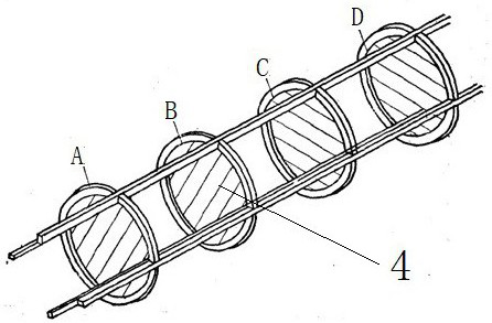
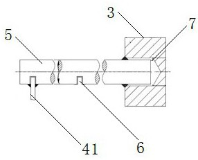
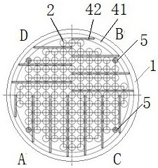
[0015] Such as figure 1 -3 shows a baffle grid connection structure of the present invention, which is used to fix the baffle grid 4 in the heat exchanger, and the heat exchanger includes a heat exchanger cylinder 1, a heat exchange tube 2, and a tube plate 3 A plurality of blind holes 7 are arranged on the tube sheet; the baffle grid 4 includes a baffle ring 41 and a baffle rod 42 . The connection structure of the baffle grid includes a plurality of spacer bars 5 arranged equiangularly in a circumferential shape, and a plurality of grooves 6 matching with the baffle grid are equidistantly arranged on the spacer bars, and the baffle grid is clamped on the In the groove and fixed by welding with the spacer bar, the spacer bar pipe limits the circle (the smallest circle surrounding all the spacer bars is the outer diameter of the circle) concentric with the baffle grid and larger than the inner diameter of the baffle grid (specifically, the baffle The inner diameter of the baff...


PUM


Abstract

The invention discloses a baffling grid connecting structure. The structure comprises a plurality of distance fixing rods, wherein grooves matching baffling grids are formed in the distance fixing rods at equal intervals, the baffling grids are clamped in the grooves and are fixed through welding, distance fixing rod pipe distribution limiting circles are concentric with the baffling grids and arelarger than the inner diameters of the baffling grids, the other ends of the distance fixing rods match blind holes formed in a tube plate and are fixed to the blind holes through welding, the four to six distance fixing rods are evenly distributed in the circumferential direction, the baffling grids are clamped in the grooves through baffling rings and are fixed through welding, the distance fixing rods are cylindrical, and the diameters of the distance fixing rods are equal to or smaller than the diameter of a heat exchange tube. The structure has the advantages that 1, the connection is reliable; 2, the rigidity of the distance fixing rods is high; 3, the positioning precision is high; and 4, the width of the baffling rings is small. By means of the structure, the defects that in the prior art, connection reliability is poor, and the heat transfer efficiency is greatly affected are effectively overcome.

Description

technical field [0001] The invention relates to the technical field of heat exchanger structures, in particular to a baffle grid connection structure. Background technique [0002] The baffle grid heat exchanger is a new type of shell-and-tube heat exchanger, which can avoid the vibration damage of the heat exchange tube caused by the use of baffles, and at the same time reduce the pressure drop of the fluid passing through the heat exchanger. The classic baffle grid heat exchanger tube bundle such as figure 1 As shown, including heat exchanger cylinder, heat exchange tubes, tube sheets, baffle grids, etc. The plane of the baffle grid is perpendicular to the heat exchange tube, and every two adjacent baffle grids limit the displacement of the heat exchange tube in a certain direction. Such as figure 1 As shown, the baffles A and B limit the horizontal displacement of the heat exchange tubes; the baffles C and D limit the vertical displacement of the heat exchange tubes. ...

Claims


Application Information

Patent Timeline
Patent Type & Authority Applications(China)
IPC IPC(8): F28F9/26F28F9/24
CPCF28F9/24F28F9/26
Inventor 王玉钱江戴洋孙志涛徐大鹿黄伟昌孟多南李秋王福新李长宝
Owner 沈阳汇博热能设备有限公司
Why Eureka
Try Eureka