Condenser with wing-shaped tube bundles arranged in cylinder
A condenser and wing-shaped technology, applied in steam/steam condensers, lighting and heating equipment, etc., can solve the problems of not reducing the heat exchange performance of the condenser, reducing the tube sheet layout rate, and high production costs. The effect of reducing the overall weight and associated costs, reducing the amount of steel used, and saving production costs
- Summary
- Abstract
- Description
- Claims
- Application Information
AI Technical Summary
Problems solved by technology
Method used
Image
Examples
specific Embodiment approach 1
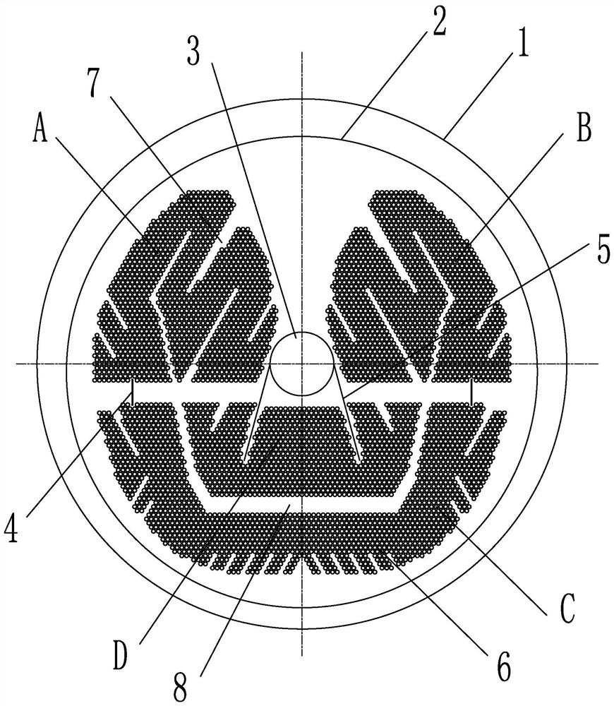
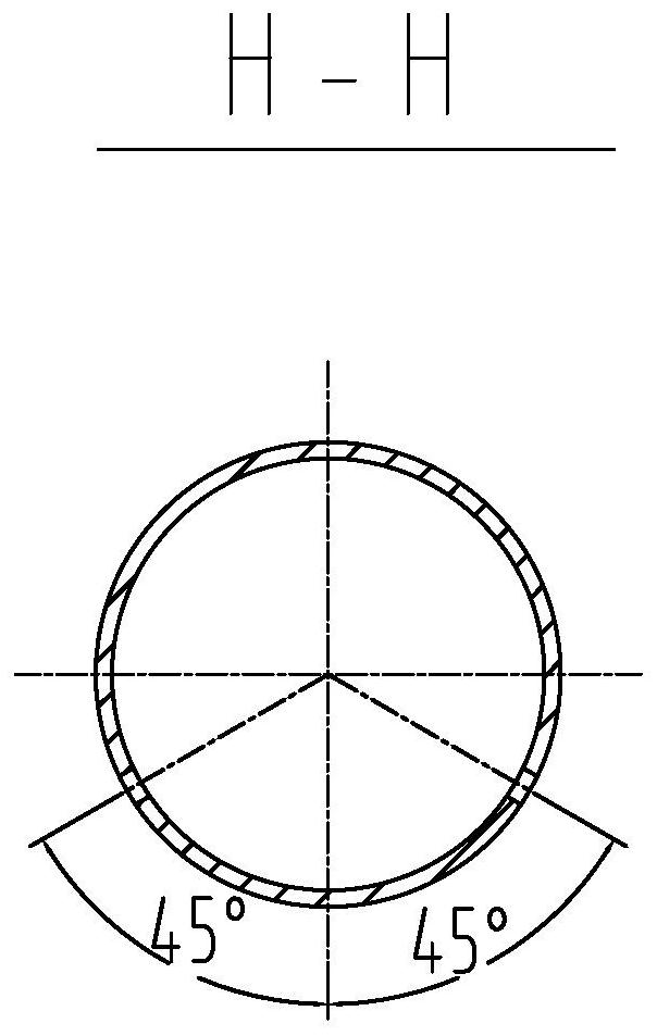
[0018] Specific implementation mode one: combine Figure 1 to Figure 5 This embodiment is described. This embodiment includes a condenser shell 1 and a tube sheet 2. The tube sheet 2 is eccentrically embedded in the condenser shell 1. It also includes an air extraction pipe 3, a main condensation area and an air cooling area D. The air extraction tube 3 is coaxially installed in the condenser cylinder 1, and the entire tube bundle is arranged on the tube plate 2 in the form of a "wing". The main condensation zone includes a plurality of heat exchange tubes 6 and two condensation baffles 4, and the plurality of heat exchange tubes 6 are arranged in a "wing-shaped" tube bundle in the form of a 60° fork row, and the "wing-shaped" tube bundle is provided with A plurality of condensing steam inlet channels 7 and a plurality of heat exchange tubes 6 form the upper left condensation zone A, the upper right condensation zone B, the lower condensation zone C, and the air cooling zone D...
specific Embodiment approach 2
[0022] Specific implementation mode two: combination figure 1 To describe this embodiment, the outer contour shape of the plurality of heat exchange tubes 6 in the main condensation zone of this embodiment is adapted to the radian of the inner cylinder of the condenser cylinder 1 . Such setting conforms to the flow boundary shape of the steam, so that the steam can better enter the inside of the tube bundle. Other components and connections are the same as those in the first embodiment.
specific Embodiment approach 3
[0023] Specific implementation mode three: combination figure 1 To illustrate this embodiment, the outer edge of the tube bundle formed by the main condensation zone and the air cooling zone D of this embodiment forms a channel with a tapering ratio of 0.5-0.7 along the axis direction of the condenser cylinder 1 . Such setting satisfies the flow law of steam condensation. During the flow process, the steam condenses continuously, and the volume occupied by the steam gradually decreases. Other compositions and connections are the same as those in Embodiment 1 or 2.
PUM
 Abstract
Description
Claims
Application Information
 - R&D
- Intellectual Property
- Life Sciences
- Materials
- Tech Scout
- Unparalleled Data Quality
- Higher Quality Content
- 60% Fewer Hallucinations
Browse by: Latest US Patents, China's latest patents, Technical Efficacy Thesaurus, Application Domain, Technology Topic, Popular Technical Reports.
© 2025 PatSnap. All rights reserved.Legal|Privacy policy|Modern Slavery Act Transparency Statement|Sitemap|About US| Contact US: help@patsnap.com


