Soil sampling device

A technology of soil sampling and sampling sleeves, applied in the direction of sampling devices, etc., can solve the problems of inconvenient sampling work, time-consuming and labor-intensive work, and achieve the effects of easy observation, less fatigue, and convenient sampling

Inactive Publication Date: 2019-02-19
安徽省公众检验研究院有限公司
11 Cites 3 Cited by

AI-Extracted Technical Summary

Problems solved by technology

[0003] However, in the process of using the traditional soil sampling device, it is time-consuming and l...

Method used

Described fixing mechanism 2 comprises limiting plate 21, connecting column 22 and fixed base 23, and described limiting plate 21 is detachably connected to the bottom of described side plate 1, and described connecting column 22 is fixed on described The end of the limiting plate 21 is away from the side plate 1 , and the fixing seat 23 is fixed on the side of the connecting column 22 away from the limiting plate 21 , which facilitates the stability of the overall structure.
Described limiting plate 21 is a cylindrical structure, and described fixed seat 23 is a conical structure, and described limiting plate 21 is set as a cylinder to facilitate described fixed seat 23 to embed too deep in the ground, and described fixed seat 23 Setting it into a cone facilitates better embedding in the ground and facilitates sampling.
Described screening mechanism 5 comprises protrusion 51, cover plate 52, hinge 53, screens out box 54, screen cloth 55, buckle 56 box collecting plate 57, and described screening box 54 is located at described second On the fixed plate 4, the cover plate 52 is rotatably connected with the screening box 54 through the hinge 53, the cover plate 52 is provided with the protrusion 51, and the screening box 54 is detachably connected with The collecting plate 57 and the screen 55 are detachably connected to the top of the collecting plate 57 through the buckle 56, so as to facilitate the screening of soil samples.
First, the device is transported to the place that needs to be sampled, the transmission mechanism 8 is placed in the middle of the first fixed plate 3 and the second fixed plate 4, the first fixed plate 3 and the second fixed plate The second fixing plate 4 is engaged, and the fixing seat 23 is embedded in the ground. The limiting plate 21 is a cylinder, which is convenient for the limiting effect with the soil, and prevents it from being inconvenient to pull out because it is too deep. The fixing seat 23 is a cone, which is conducive to diving into the soil, so that the overall structure is more stable. The crank handle 71 is fixed on the driving column 81, and the crank handle 71 is provided with the anti-slip sleeve 72, so The anti-slip sleeve 72 is provided with the anti-slip protrusion 73, and the anti-slip protrusion 73 is a hemispherical shape containing a cavity, which is convenient for relieving fatigue during use. One end of the connecting column 22 is fixed to the drive Column 81, the other end extends to the inside of the slide bar 83 and is threadedly connected with the slide bar 83, the slide bar 83 is slidably connected with the slide sleeve 84, and the handle 71 is rotated, and the handle 71 drives The driving column 81 rotates, the driving column 81 drives the connecting column 22 to rotate, the sliding rod 83 slides in the sliding sleeve 84, drives the sampling mechanism 9 to move downward for sampling, and the drill bit 92 is a cone, which is convenient for sampling. The sampling sleeve 91 is detachably connected ...

Abstract

The invention provides a soil sampling device. The soil sampling device comprises side plates, fixing mechanisms, a first fixing plate, a second fixing plate, a screening mechanism, an observation table, a shaking mechanism, a driving mechanism, and a sampling mechanism. The second fixing plate and the first fixing plate are symmetrically arranged around the side plates, and the second fixing plate is clamped with the first fixing plate. The screening mechanism is arranged at the second fixing plate. The observation table is arranged at the second fixing plate in a position adjacent to the screening mechanism. The shaking mechanism is fixed in the middle of the first fixing plate and the second fixing plate. The driving mechanism is fixed to one end, which is close to the fixing mechanism,of the shaking mechanism. The sampling mechanism comprises a sampling sleeve, a drilling bit, and a protective cover. According to the soil sampling device, the device is a time-saving and labor-saving soil sampling device, and is convenient for taking multiple sets of samples at one time.

Application Domain

Technology Topic

Image

  • Soil sampling device
  • Soil sampling device
  • Soil sampling device

Examples

  • Experimental program(1)

Example Embodiment

[0023] The present invention will be further described below with reference to the drawings and embodiments.
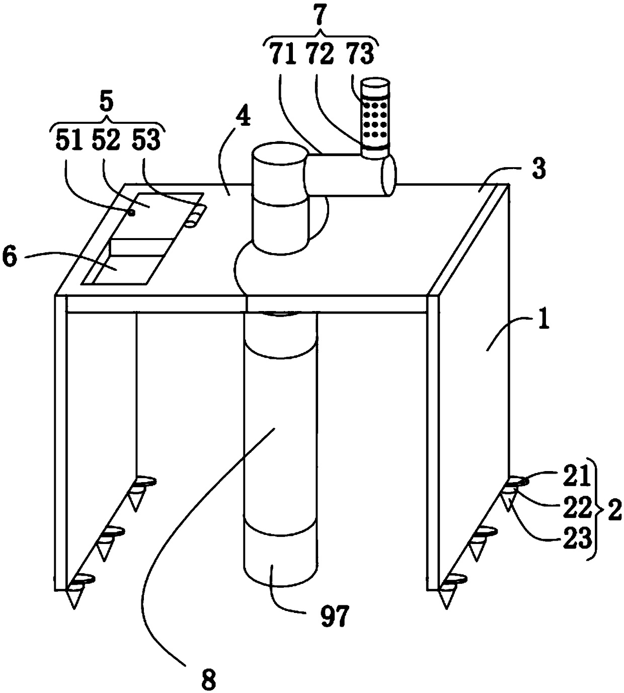
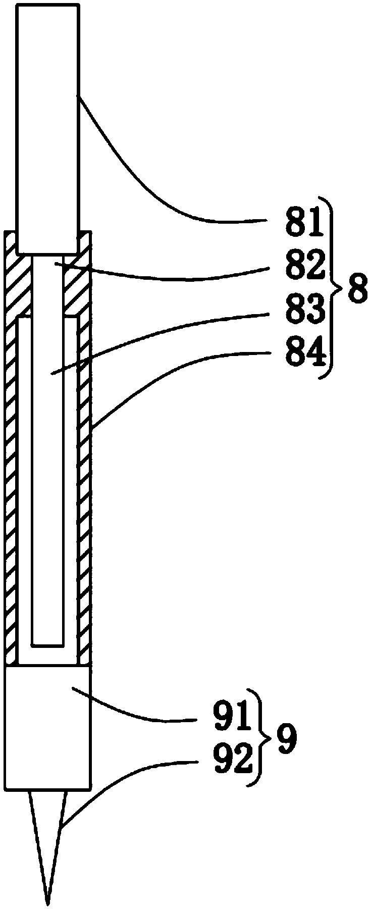
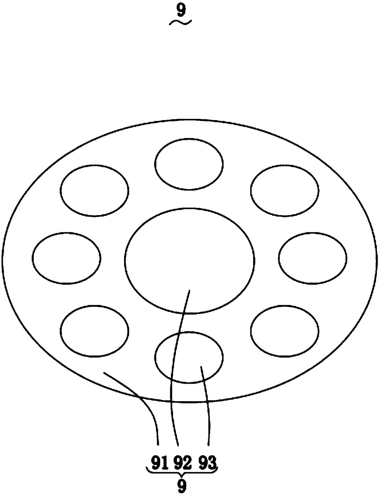
[0024] Please refer to figure 1 , figure 2 , image 3 , Figure 4 with Figure 5 , The soil sampling device includes: a side plate 1; a fixing mechanism 2, the fixing mechanism 2 is symmetrically arranged at the bottom end of the side plate 1, and the fixing mechanism 2 is detachably connected to the side plate 1; Plate 3, the first fixing plate 3 is fixed to the side wall of the side plate 1 facing away from the fixing mechanism 2; the second fixing plate 4, the second fixing plate 4 and the first fixing plate 3 The side plate 1 is symmetrically arranged, and the second fixing plate 4 is engaged with the first fixing plate 3; a screening mechanism 5, the screening mechanism 5 is arranged on the second fixing plate 4; Observation platform 6, the observation platform 6 is set on the second fixed plate 4 adjacent to the screening mechanism 5; a shaking mechanism 7, the shaking mechanism 7 is fixed on the first fixed plate 3 and The middle of the second fixed plate 4; the transmission mechanism 8, the transmission mechanism 8 is fixed to the end of the shaking mechanism 7 close to the fixing mechanism 2; the sampling mechanism 9, the sampling mechanism 9 is detachably connected to the transmission An end of the mechanism 8 facing away from the shaking mechanism 7, the sampling mechanism 9 includes a sampling sleeve 91, a drill bit 92 and a protective cover 97, the sampling sleeve 91 is detachably connected to the end of the transmission mechanism 8 facing away from the shaking mechanism 7, so The drill bit 92 is arranged in the sampling sleeve 91, the protective cover 97 is slidably connected to the sampling sleeve 91, and the protective cover 97 is engaged with the sampling sleeve 91.
[0025] The fixing mechanism 2 includes a limiting plate 21, a connecting column 22, and a fixing seat 23. The limiting plate 21 is detachably connected to the bottom end of the side plate 1, and the connecting column 22 is fixed to the limiting plate. The end 21 is far away from the side plate 1, and the fixing seat 23 is fixed on the side of the connecting column 22 away from the limiting plate 21 to facilitate the stability of the overall structure.
[0026] The limiting plate 21 is a cylindrical structure, the fixing seat 23 is a conical structure, the limiting plate 21 is configured as a cylinder to facilitate the fixing seat 23 to be embedded in the ground too deeply, and the fixing seat 23 is set to be a cone The body can be better embedded in the land and is convenient for sampling.
[0027] The screening mechanism 5 includes a protrusion 51, a cover 52, a hinge 53, a screening box 54, a screen 55, a buckle 56 and a collection plate 57. The screening box 54 is provided on the second fixing plate 4 In the above, the cover plate 52 is rotatably connected to the screening box 54 through the hinge 53, the cover plate 52 is provided with the protrusion 51, and the screening box 54 is detachably connected with the collection box 54 A plate 57. The screen 55 is detachably connected to the top of the collection plate 57 through the buckle 56 to facilitate screening of soil samples.
[0028] The rocking mechanism 7 includes a rocking handle 71, a non-slip sleeve 72 and a non-slip protrusion 73. The rocking handle 71 is fixed to the transmission mechanism 8, and the rocking handle 71 is provided with the non-slip sleeve 72, The non-slip sleeve 72 is provided with the non-slip protrusion 73, which is beneficial to prevent slippage during use.
[0029] The anti-slip protrusion 73 is a hemispherical shape with a cavity inside, which is beneficial to reduce fatigue during use.
[0030] The transmission mechanism 8 includes a driving column 81, a connecting column 22, a sliding rod 83 and a sliding sleeve 84. The driving column 81 is fixed to the crank 71, and one end of the connecting column 22 is fixed to the driving column 81, The other end extends to the inside of the sliding rod 83 and is threadedly connected with the sliding rod 83, and the sliding rod 83 is slidably connected with the sliding sleeve 84 to facilitate the control of the sampling depth.
[0031] The cross-sectional area of ​​the connecting rod is smaller than the cross-sectional area of ​​the driving column 81 and the sliding rod 83, which is convenient for controlling the stability during the sampling process.
[0032] The sampling mechanism 9 further includes a collection tank 93, a sampling port 94, a bolt 95, and a sampling tip 96. The collection tank 93 is provided in the sampling sleeve 91 and is threadedly connected to the sampling sleeve 91. The sampling port 94 is provided on the 93, the bolt 95 is provided on one side of the sampling port 94, and the sampling tip is fixed to the bottom end of the collection tank 93, which is convenient for taking multiple sets of samples at the same time.
[0033] The working principle of the soil sampling device provided by the present invention is as follows:
[0034] First, transport the device to the place where sampling is required, place the transmission mechanism 8 between the first fixed plate 3 and the second fixed plate 4, and connect the first fixed plate 3 and the second fixed plate 3 The two fixing plates 4 are engaged, and the fixing seat 23 is embedded in the ground. The limiting plate 21 is a cylinder, which facilitates the limiting function with the soil and prevents the inconvenience of pulling out due to the sinking too deep. The seat 23 is a cone, which is conducive to diving into the soil and makes the overall structure more stable. The crank 71 is fixed to the driving column 81, and the anti-slip sleeve 72 is provided on the crank 71. The anti-slip protrusion 73 is provided on 72, and the anti-slip protrusion 73 is a hemispherical accommodating cavity, which is convenient for reducing fatigue during use. One end of the connecting column 22 is fixed to the driving column 81, The other end extends to the inside of the sliding rod 83 and is threadedly connected with the sliding rod 83. The sliding rod 83 is slidably connected with the sliding sleeve 84, and the crank 71 is rotated, and the crank 71 drives the drive The column 81 rotates, the driving column 81 drives the connecting column 22 to rotate, the sliding rod 83 slides in the sliding sleeve 84, and drives the sampling mechanism 9 to move downward for sampling. The drill 92 is a cone The sampling sleeve 91 is detachably connected to the bottom end of the sliding sleeve 84, the collection tank 93 is provided in the sampling sleeve 91, and the sampling port 94 is provided on the collection tank 93. The sampling port 94 is closed by the bolt 95, the sampling tip 96 is set as a cone to facilitate sampling, and a plurality of the collection grooves 93 are provided to facilitate simultaneous collection of multiple samples. The collecting groove 93 is screwed to the sampling sleeve 91. After sampling, the collecting groove 93 is removed, the sampling port 94 is opened, and the sample is taken out. The protective cover 97 is used to prevent the sampling sleeve 91 from Protect it during use. Place the taken sample on the observation platform 6 for observation. When the sample needs to be screened out, put the sample in the screening box 54 and pass it through the screen 55. In addition, collection is performed through the collection plate 57.
[0035] Compared with related technologies, the soil sampling device provided by the present invention has the following beneficial effects:
[0036] The present invention provides a soil sampling device. The fixing seat 23 is a pyramid, which is easy to be embedded in the ground. The limiting plate 21 is a cylinder, which is convenient for the fixing seat 23 to be embedded in the ground too deeply. The first fixing plate 3 is engaged with the second fixing plate 4, and the driving column 81 is fixed between the engagement openings of the first fixing plate 3 and the second fixing plate 4 for easy fixing. The crank 71 is provided with There is the protective cover, the non-slip sleeve 72 is provided with the non-slip protrusions 73, and the non-slip protrusions 73 are hemispherical with a cavity inside, which is convenient for reducing fatigue during use. The drill 92 It is a cone, which is convenient for sampling. The collection sleeve is provided with a plurality of the collection grooves 93 for collecting multiple samples at the same time. The collection grooves 93 are threadedly connected to the sampling sleeve 91 to facilitate the The collection tank 93 is removed, the sampling port 94 is opened, and the sample is taken out. The observation platform 6 is also provided on the second fixed plate 4 to facilitate the observation of the sample. When the sample needs to be screened out , Put the sample into the screening box 54, pass through the screen 55 for screening, and pass through the collection plate 57 for collection.
[0037] The electrical components appearing in this application are all connected to an external power source when in use.
[0038] The motor adopts the 6IK180RGU/6GU40K model and related supporting power supply and circuit provided by Pengcheng Tmall flagship store.
[0039] The circuits and electrical components and modules involved are all existing technologies that can be implemented by those skilled in the art. Needless to say, the content protected by the present invention does not involve improvements to software and methods.
[0040] The above are only the embodiments of the present invention, and do not limit the scope of the present invention. Any equivalent structure or equivalent process transformation made using the content of the description and drawings of the present invention, or directly or indirectly applied to other related technologies In the same way, all fields are included in the scope of patent protection of the present invention.

PUM

no PUM

Description & Claims & Application Information

We can also present the details of the Description, Claims and Application information to help users get a comprehensive understanding of the technical details of the patent, such as background art, summary of invention, brief description of drawings, description of embodiments, and other original content. On the other hand, users can also determine the specific scope of protection of the technology through the list of claims; as well as understand the changes in the life cycle of the technology with the presentation of the patent timeline. Login to view more.

Similar technology patents

Horizontal type cervical vertebra traction bed adaptive to physiological curvature of cervical vertebrae

ActiveCN104083240AGood for treatment purposesReduce fatigueChiropractic devicesFractureVertebraDisease
Owner:THE AFFILIATED HOSPITAL TO CHANGCHUN UNIV OF CHINESE MEDICINE

A syringe capable of quantitatively injecting drugs

PendingCN109125860AReduce fatigueOvercome the trouble of tedious extraction of liquid medicineAutomatic syringesMedical devicesDrugPiston
Owner:FOSHAN UNIVERSITY

Classification and recommendation of technical efficacy words

  • Reduce fatigue
  • Sampling is convenient

Dictation selection

Owner:DELIVERHEALTH SOLUTIONS LLC

Locking hinge connector apparatus

InactiveUS20060016047A1Reduce back strainReduce fatigueBrush bodiesHingesHinge angleEngineering
Owner:BLACKMAN GARY PALMER +1

Kit for detecting colorectal cancer and precancerous lesions and use method thereof

PendingCN109097471AReduce the rate of missed diagnosis and missed detectionSampling is convenientMicrobiological testing/measurementBiological testingKRAS Gene MutationSulfite
Owner:HANGZHOU HEYI GENE TECH

People also interested in

Why Eureka
Try Eureka