Supercharge Your Innovation With Domain-Expert AI Agents!

Forward Target Detection Radar and Method

A target detection and target technology, applied in the field of vehicle radar, can solve the problems of low detection accuracy and small coverage of target detection devices, and achieve the effect of increasing the detection range, ensuring accuracy and improving accuracy

Active Publication Date: 2020-10-16
WHST CO LTD
View PDF10 Cites 0 Cited by
  • Summary
  • Abstract
  • Description
  • Claims
  • Application Information

AI Technical Summary

Problems solved by technology

[0004] In view of this, the embodiment of the present invention provides a forward target detection radar and method to solve the problems of small coverage and low detection accuracy of target detection devices in the prior art

Method used


Image

  • Forward Target Detection Radar and Method
  • Forward Target Detection Radar and Method
  • Forward Target Detection Radar and Method

Examples


Embodiment 1

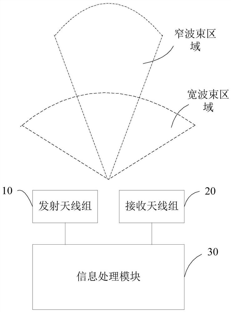
[0054] This embodiment provides a forward target detection radar, which is suitable for equipment such as forward emergency braking or forward collision warning of vehicles. see figure 1 , is a schematic structural diagram of the forward target detection radar in this embodiment. For ease of description, only the parts related to this embodiment are shown.

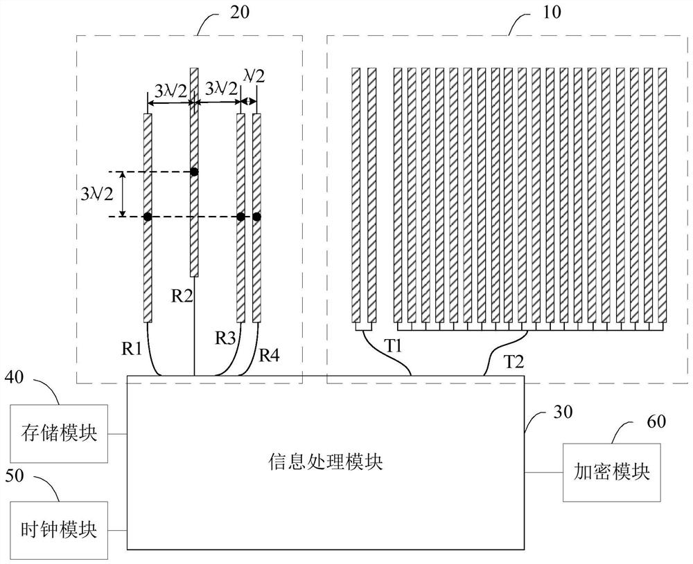
[0055] The forward target detection radar includes: a transmitting antenna group 10 , a receiving antenna group 20 and an information processing module 30 .

[0056] The transmitting antenna group 10 uses the millimeter wave modulation signal sent by the information processing module 30 to scan the targets in the wide beam area and the narrow beam area; the receiving antenna group 20 receives the wide beam echo signal of the target in the wide beam area and the narrow beam area The narrow beam echo signal of the inner target is sent to the information processing module 30 .

[0057] The information processing module 30 ...

Embodiment 2

[0110] Corresponding to the forward target detection radar described in Embodiment 1 above, image 3 A schematic diagram of the implementation flow of an embodiment of the forward target detection method is provided, which is described in detail as follows:

[0111] In step S301, the transmitting antenna group uses the millimeter wave modulation signal to scan the target in the wide beam area and the narrow beam area.

[0112] In specific applications, compared with infrared and laser, millimeter-wave modulation signals have a stronger ability to penetrate fog, smoke, and dust, and have the characteristics of all-weather and all-weather, and have strong anti-interference ability.

[0113] Step S302, acquiring the wide-beam echo signal of the target in the wide-beam area and the narrow-beam echo signal of the target in the narrow-beam area through the receiving antenna group.

[0114] Step S303, perform target positioning on the wide-beam echo signal to obtain wide-beam target...


PUM


Abstract

The invention is suitable to the technical field of vehicle-mounted radar, and provides a forward target detecting radar and a method. The forward target detecting radar comprises: a transmitting antenna group, a receiving antenna group and an information processing module. The transmitting antenna group is used for scanning a target in the wide beam area and the narrow beam area by using the millimeter wave modulation signal sent by an information processing module. The receiving antenna group is used for receiving the wide beam echo signals of the target in the wide beam area and the narrowbeam echo signals of the target in the narrow beam area and sending to the information processing module. The information processing module is used for performing target positioning on the wide beam echo signals to obtain the wide beam target position information, performing target positioning on the narrow beam echo signals to obtain the narrow beam target position information, and fusing the wide beam target position information and the narrow beam target position information through a secondary clustering algorithm to determine the target information. According to the forward target detecting radar, the coverage range for detecting the target is large, the target detecting precision is high, and the millimeter wave is not affected by meteorological conditions, so that the driving safetyof the vehicle is guaranteed.

Description

technical field [0001] The invention belongs to the technical field of vehicle radar, and in particular relates to a forward target detection radar and a method. Background technique [0002] With the vigorous development of the automobile industry, major automobile companies are focusing on the research and development of forward target detection radar systems, aiming to reduce traffic accidents, improve road traffic safety and enhance road traffic capacity. [0003] Vehicle forward target detection devices include video recognition, laser radar, ultrasonic radar, etc., but the target detection devices currently on the market have a small coverage and low detection accuracy, which reduces the performance of the radar; for example, video recognition is seriously affected by light, and the line of sight is not ideal Under the circumstances, the accuracy of target positioning is low; LiDAR is greatly affected by light and weather, and the performance of LiDAR is greatly reduce...

Claims


Application Information

Patent Timeline
Patent Type & Authority Patents(China)
IPC IPC(8): G01S13/00G01S13/931G01S7/40G01S7/41
CPCG01S7/4052G01S13/00G01S13/931
Inventor 秦屹邢寒露樊志博周春霞安国玉
Owner WHST CO LTD
Features
  • R&D
  • Intellectual Property
  • Life Sciences
  • Materials
  • Tech Scout
  • Unparalleled Data Quality
  • Higher Quality Content
  • 60% Fewer Hallucinations
Learn More