Arc extinguishing mechanism and direct-current circuit breaker

A DC circuit breaker and arc extinguishing technology, which is applied to circuit breaker parts, circuits, electrical components, etc., can solve problems such as elongated arc, aggravated burning of moving contacts, and inability to cut arc extinguishing grids, so as to achieve reliable breaking , to solve the effect of long arcing time

Active Publication Date: 2019-02-19
BEIJING PEOPLES ELECTRIC PLANT
View PDF15 Cites 6 Cited by
  • Summary
  • Abstract
  • Description
  • Claims
  • Application Information

AI Technical Summary

Problems solved by technology

[0003] In the existing known technologies, technical means such as extending the arc by increasing the opening distance, promoting and cooling the arc by burning gas-generating materials, and promoting the arc by increasing the magnetic field have appeared. In limited circumstances, these methods will not reliably break the circuit
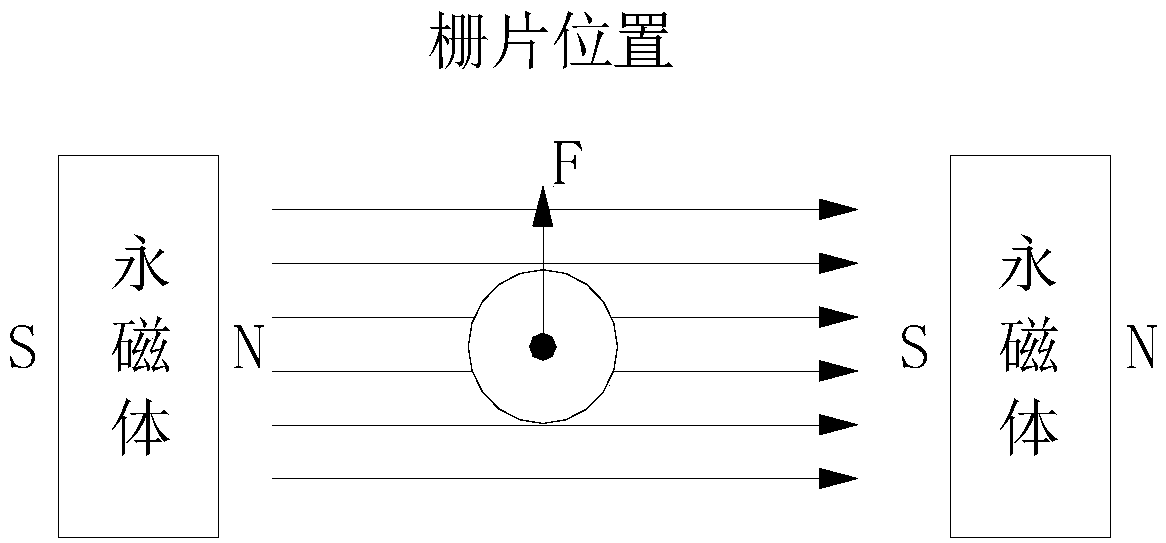
In the technical scheme of enhancing the magnetic field, the magnetic field in the arcing area is enhanced by adding permanent magnets, which generates a thrust on the arc and pushes the arc to the arc extinguishing grid; figure 1 In the structure shown, two permanent magnets are placed opposite each other, and the magnetic field lines start from the N pole and return to the S pole. When the current is positive ( figure 1 When the direction shown is positive), the magnetic field generated by the permanent magnet will push the arc to move toward the arc extinguishing grid to achieve the purpose of arc extinguishing; but when the current is reversed, the magnetic field generated by the permanent magnet will push the arc to extinguish the arc If the grid moves in the opposite direction, the arc cannot enter the arc extinguishing chamber, causing the arc extinguishing grid to cut and cool the arc, and the arc cannot be extinguished. At the same time, it will greatly aggravate the burning of the rear moving contact; therefore, this method must be forced Specify the polarity of the incoming and outgoing lines, such as reverse connection will lead to extremely serious accidents

Method used


Image

  • Arc extinguishing mechanism and direct-current circuit breaker
  • Arc extinguishing mechanism and direct-current circuit breaker
  • Arc extinguishing mechanism and direct-current circuit breaker

Examples


Embodiment Construction

[0060] The following will clearly and completely describe the technical solutions in the embodiments of the application with reference to the accompanying drawings in the embodiments of the application. Apparently, the described embodiments are only part of the embodiments of the application, not all of them. Based on the implementation manners in this application, all other implementation manners obtained by persons of ordinary skill in the art without creative efforts fall within the scope of protection of this application.

[0061] It should be noted that when an element is referred to as being “disposed on” another element, it may be directly on the other element or there may also be an intervening element. When an element is referred to as being "connected to" another element, it can be directly connected to the other element or intervening elements may also be present. The terms "vertical," "horizontal," "left," "right," and similar expressions are used herein for purpos...


PUM


Abstract

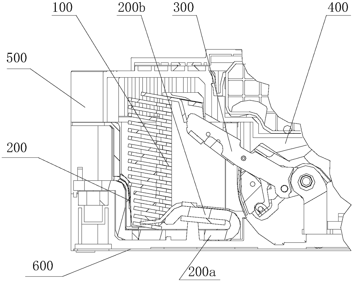
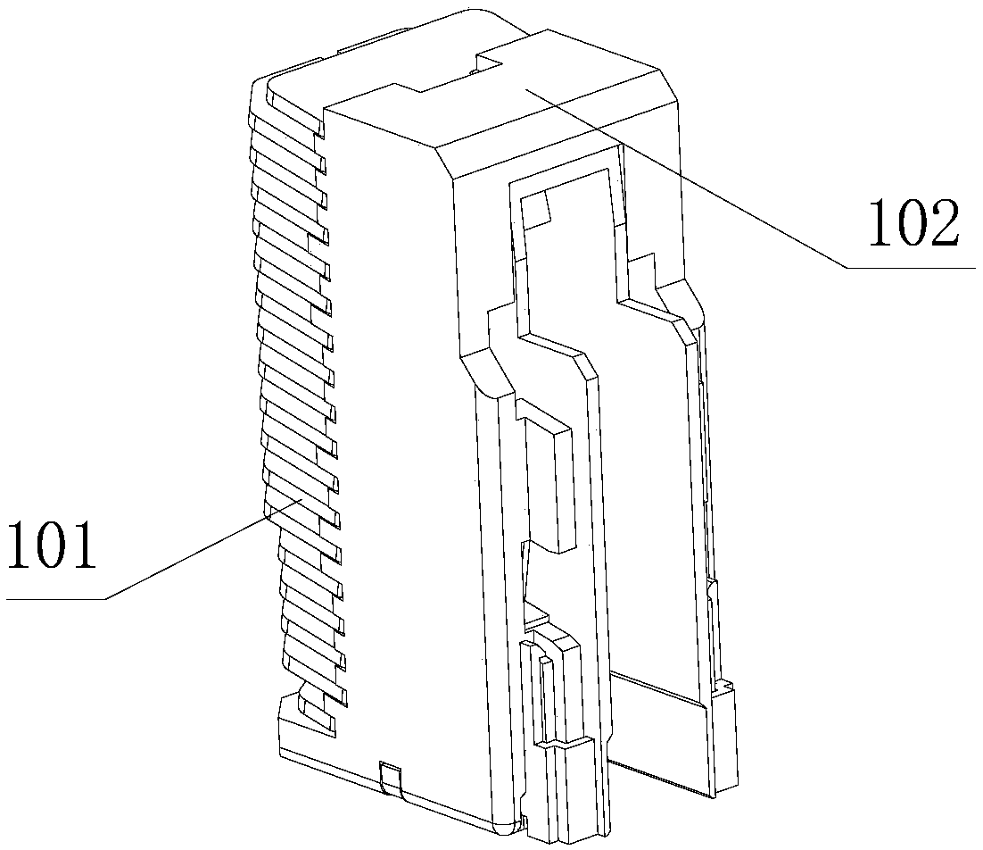
The invention provides an arc extinguishing mechanism and a direct-current circuit breaker. The arc extinguishing mechanism comprises a fixed contact, a movable contact and a permanent magnet. The fixed contact comprises a base and a bending portion positioned at a first quadrant of the base, and the bending portion is provided with an electric contact. The movable contact can rotate relative to the fixed contact, so that electric contacts of the movable contact and the fixed contact are in contact and / or separation, and a plane formed by rotation of the movable contact is a reference plane. The permanent magnet is provided with a first magnetic pole and a second magnetic pole opposite to the first magnetic pole, and the connecting line of the first magnetic pole and the second magnetic pole is not perpendicular to the reference plane. The direct-current circuit breaker comprises a substrate, a shell, a plurality of laminated gate pieces and the arc extinguishing mechanism. The arc extinguishing mechanism and the direct-current circuit breaker can effectively solve the problem of long low-current critical breaking arc duration of direct-current high voltage, and reliable breaking under the condition of forward and reverse current can be ensured.

Description

technical field [0001] The application belongs to the technical field of low-voltage electrical appliances, and in particular relates to an arc extinguishing mechanism and a DC circuit breaker used in a low-voltage DC circuit breaker. Background technique [0002] A circuit breaker is a switching device that can carry and break current under normal circuit conditions, and can also carry and break current under abnormal circuit conditions within a specified time. With the development of new energy technology, the rated operating voltage of DC circuit breakers is getting higher and higher, which has reached 1500V at present. With the increase of working voltage, the market puts forward higher requirements for the reliable breaking performance of circuit breakers, and the difficulty of critical breaking will increase significantly. At present, when the common low-voltage DC circuit breaker breaks a small current of 4A-63A under the condition of rated working voltage and time c...

Claims


Application Information

Patent Timeline
Patent Type & Authority Applications(China)
IPC IPC(8): H01H9/44H01H9/34H01H73/18
CPCH01H9/34H01H9/443H01H73/18
Inventor 南寅刘万里王喜成赵小苇
Owner BEIJING PEOPLES ELECTRIC PLANT
Why Eureka
Try Eureka