Sensor for detecting belt rupture

a technology of sensor and belt, which is applied in the direction of alarm, dynamo-electric machines, washing apparatus, etc., can solve the problems of inability to operate the sensor in a functionally reliable manner, unstable switching state, and extremely slow switch actuation, so as to achieve less sensitive and economical sensor production

Inactive Publication Date: 2005-07-28
MARQUARDT GMBH SCHLOSSTRASSE 16 7201 RIETHEIM-WEILHEIM 1 WEST GERMANY
View PDF9 Cites 5 Cited by
  • Summary
  • Abstract
  • Description
  • Claims
  • Application Information

AI Technical Summary

Benefits of technology

[0010] The solution as claimed in the invention avoids the aforementioned disadvantages, in that a particular bistable snap-action system with a cascade is used as the contact system. By means of the offset of the two clamped points on the carrier part, the leaf spring-like switching contact actuated by the transmission element snaps over the first time the dead point is passed over. In the region of the dead point, on the side of the contact surface on the switching contact, as a result of the offset of the clamping points there is always still sufficient contact force in order to carry the applied current safely. Furthermore, even in the event of extremely slow actuation of the switch, it is ensured that, until the switching point, there is sufficient contact force applied to the switching contact in order to carry the current of the electric motor. When the side of the switching contact that faces the transmission element snaps over, the side of the switching contact that faces the contact surface is also guided abruptly over its dead point and the circuit is reliably broken. Because of the bistable nature, impermissible switching to and fro of the contact system in the region of the switching point is also avoided.
[0011] Thus, the transmission element can be formed as a lever mounted on one side, a roller for guiding the belt being arranged on the end of the lever opposite the bearing. The transmission element is loaded in the direction of the switching contact by means of an elastic element, to be specific in particular by means of a tension spring. An arrangement of this type ensures immediate and undelayed switching of the contact system by the transmission element following the rupture of the belt.
[0014] In further refinement, during its movement, the transmission element can act on an actuating element, which is mounted on the housing such that it can move, to be specific in particular in a housing attachment on the base. The actuating element then acts in turn by means of a pin on the second end of the leaf spring having the contact surface in order to switch the contact system. As a result, the housing with contact system and actuating element can be provided as a preassembled component, in order then to permit simple final installation in the entire subassembly for the sensor.
[0017] The advantages achieved by the invention, in addition to the improvements already cited, consist in particular in the fact that the sensor is less sensitive with respect to tolerances with regard to the length of the belt. In spite of the simple configuration, the sensor has a precisely defined switching point. When it switches over, the contact system carries out abrupt electrical opening between switching and fixed contacts, so that a changeover is achieved even in the case of welded contacts. Finally, even as compared with solutions with conventional switches, critical situations with regard to heating shortly before the switching point are reliably avoided. The sensor as claimed in the invention therefore operates in a more functionally reliable manner than previous sensors. In addition, the sensor can be produced economically.

Problems solved by technology

This can lead to the sensor not operating in a functionally reliable manner.
In the event of impermissible lengthening of the belt, there is additionally the danger that the switch will be actuated extremely slowly and (in particular when the conventional switch is used) in the event of remaining shortly before the switching point, will be operated in the region of a contact force of zero.
As a result, an uncertain switching state is produced, as is the danger of contact welding.
In addition, there is a danger of multiple switching on and off during operation in this limiting range as a result of a slight to and fro movement of the tensioning device.

Method used


Image

  • Sensor for detecting belt rupture
  • Sensor for detecting belt rupture
  • Sensor for detecting belt rupture

Examples


Embodiment Construction

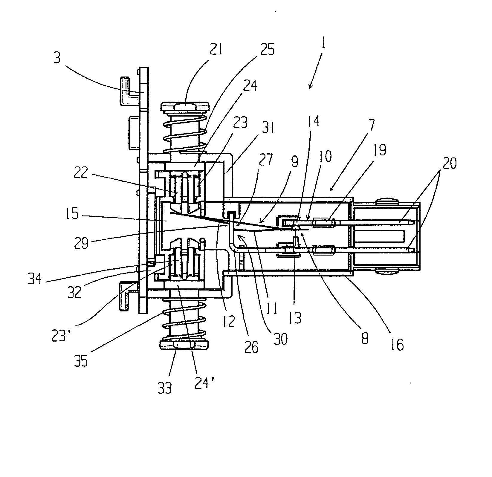
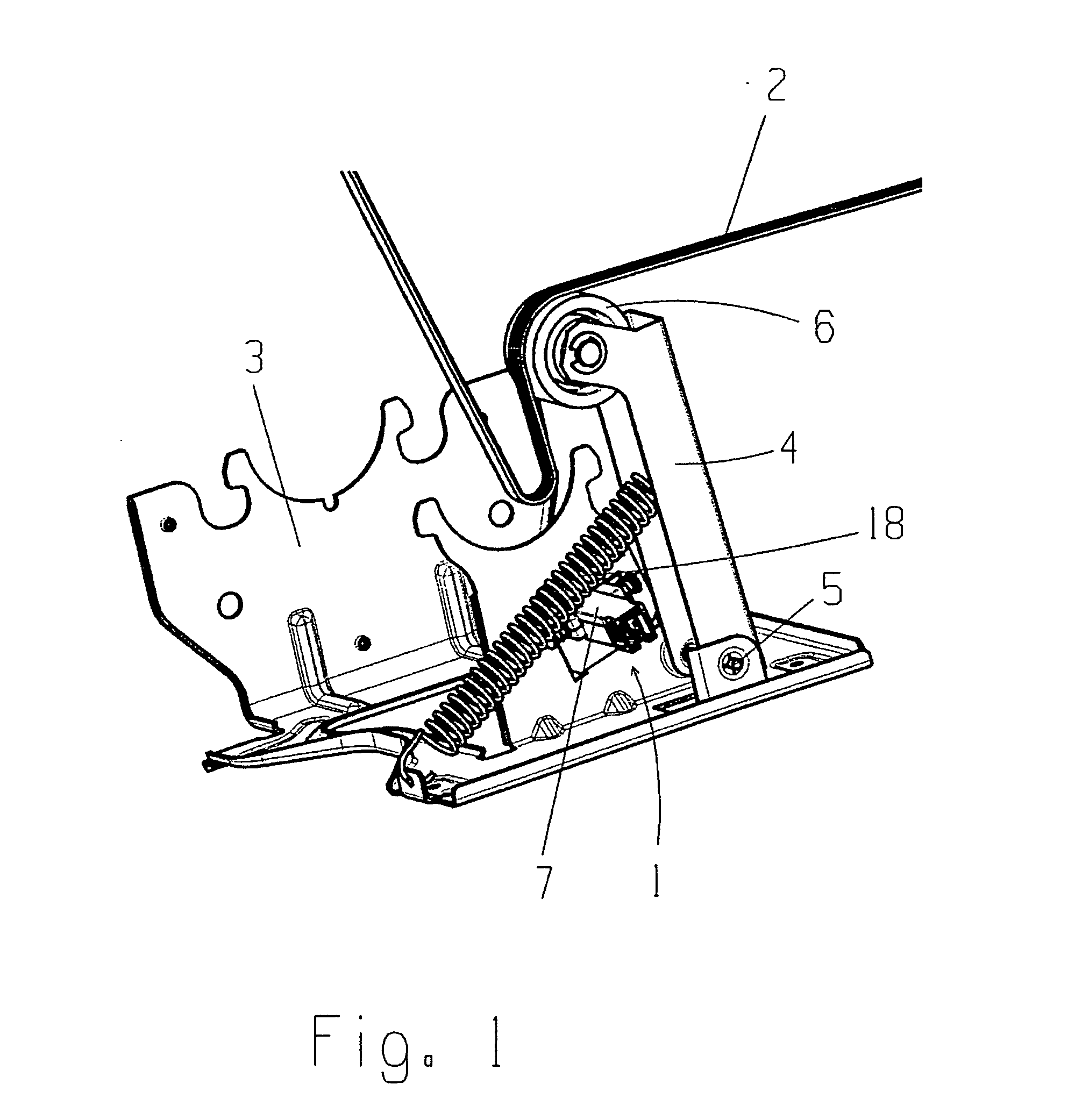
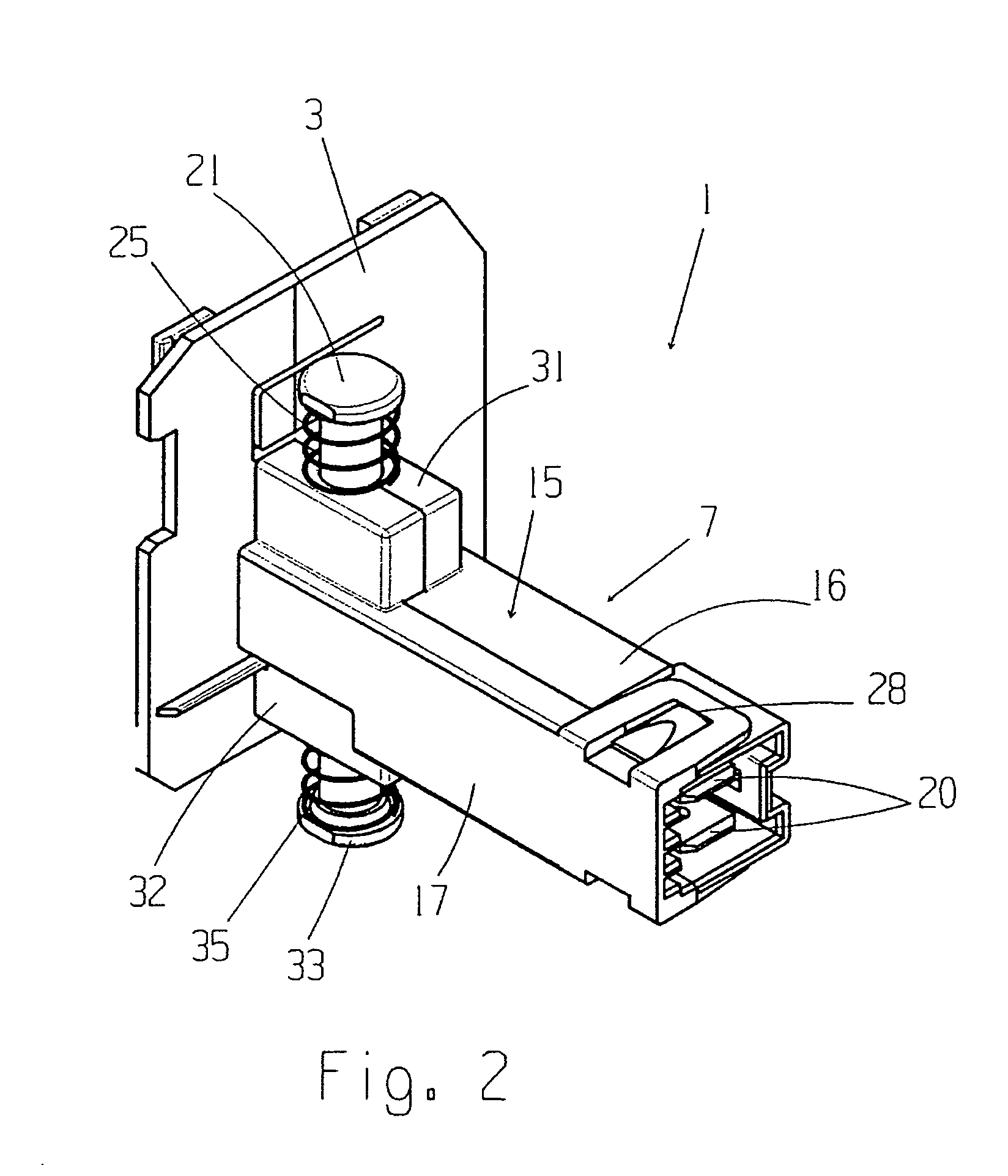
[0024] In order to drive a drum in a tumble dryer, washing machine or another domestic appliance, use is made of an electric motor which moves the drum via a drive belt. In order to detect a rupture and / or an impermissible length change of the drive belt, use is made of a sensor 1 for detecting a rupture and / or a length change in a belt 2, as can be seen in FIG. 1.

[0025] The sensor 1 is fixed in a holder 3 in the domestic appliance, like the tumble dryer, the washing machine or the like. Arranged on the holder 3 is a movable transmission element 4 which is operatively connected to the belt 2. For this purpose, the transmission element 4 is formed as a lever mounted on one side on the holder 3 such that it can rotate. Arranged at the end of the lever of the transmission element 4 opposite the bearing 5 is a roller 6, on which the belt 2 is guided along. In the event of an impermissible length change and / or a rupture of the belt 2, the position of the transmission element 4 changes a...


PUM

PropertyMeasurementUnit
length changeaaaaaaaaaa
lengthaaaaaaaaaa
electricaaaaaaaaaa

Abstract

A sensor for detecting a rupture or length change in a belt. The sensor has a movable transmission element operatively connected to the belt, that acts on an electrical switch having a contact system in the event of a length change or rupture of the belt. The contact system comprises a switching contact with a contact surface arranged on a first end, and an associated fixed contact. The transmission element acts on the second end of the leaf spring. A limb extends approximately from the first end of the leaf spring in the direction of the second end, and a further limb extends from the second end of the leaf spring in the direction of the first end. The free ends of the two limbs are clamped offset from one another on a carrier part of the switch, such that the switching contact switches over in a bistable manner.

Description

CROSS REFERENCE TO RELATED APPLICATIONS [0001] This application is a continuation of International Application No. PCT / DE2003 / 002298, having an international filing date of Jul. 9, 2003, which designated the United States, the entirety of which is incorporated herein by reference. [0002] This application also claims the benefit of German Application No. 102 31 078.5, having a filing date of Jul. 10, 2002, the entirety of which is incorporated herein by reference.FIELD OF THE INVENTION [0003] The invention relates to a sensor for detecting rupture and / or a length change in a belt. More specifically, the invention relates to a sensor with a movable transmission operatively connected to the belt that acts on an electrical switch in the event of a length change or rupture of the belt. BACKGROUND OF THE INVENTION [0004] In domestic electrical appliances, such as in a tumble dryer, a washing machine or the like, the drum is driven by means of an electric motor via a drive belt. The drive ...

Claims


Application Information

Patent Timeline
Patent Type & Authority Applications(United States)
IPC IPC(8): D06F58/08F16H7/08F16H7/12F16P7/02G01N3/00G01N3/08
CPCD06F58/08F16H7/1281F16H2007/0808F16H2007/0861F16H2061/1208F16P7/02F16H2057/014G01N2203/0017G01N2203/005G01N2203/0067G01N2203/0282F16H57/01G01N3/08
Inventor MULLER, HEINRICHLONAU, MANFRED
Owner MARQUARDT GMBH SCHLOSSTRASSE 16 7201 RIETHEIM-WEILHEIM 1 WEST GERMANY
Why Eureka
Try Eureka