Medium voltage DC vacuum circuit breaker main circuit topology and breaking method thereof

A technology for vacuum circuit breakers and main circuits, applied in emergency protection circuit devices, electrical components, etc., can solve the problems of small equivalent impedance of circuit breakers, high volt-second product performance, difficult to achieve magnetic characteristics, etc., and improve the breaking reliability. , the effect of reducing the volume and cost, and facilitating the structural arrangement

Active Publication Date: 2019-11-01
WUHAN MARINE ELECTRIC PROPULSION RES INST CHINA SHIPBUILDING IND CORP NO 712 INST
View PDF4 Cites 5 Cited by
  • Summary
  • Abstract
  • Description
  • Claims
  • Application Information

AI Technical Summary

Problems solved by technology

but in Figure 4 In the scheme shown, since the saturable reactor is connected in series with the vacuum circuit breaker, it needs to conduct the load current for a long time, which will generate additional heat loss; and in the working process of the saturable reactor, it is required to be able to Before the excitation current decreases to zero (inflection point current), it quickly exits the saturation state, and has a high volt-second product performance, which is quite different from the thyristor valve anode saturated reactor commonly used in the current power system; especially when reacting When the volume requirement of the reactor is high, it is difficult to achieve the corresponding magnetic characteristics; and when the load current is as high as several kA, it has to be considered to configure the reactor with water cooling equipment
exist Figure 5 In the scheme shown, when the arcing current of the vacuum circuit breaker is large and the current drop rate is high, the vacuum gap is likely to be unable to recover the dielectric strength immediately after the arc current crosses zero, resulting in a small equivalent impedance after the arc of the circuit breaker; Considering the effect of the equivalent impedance of the actual diode branch, when the two are of the same order of magnitude, there may still be a small part of the reverse arc current flowing through the vacuum gap during the diode freewheeling period, and the vacuum gap cannot perform dielectric recovery, so The voltage clamping effect of the diode fails to play a practical role; at the same time, because the diode is an uncontrolled device, it is naturally turned on when the voltage is positive, so this scheme is difficult to realize the bidirectional symmetrical breaking function of the DC vacuum circuit breaker
Image 6 The scheme shown has a limited effect on the improvement of the forced commutation breaking characteristics of DC vacuum circuit breakers under the conditions of high current and high current drop rate, and is usually only used as an auxiliary measure for a specific scheme

Method used


Image

  • Medium voltage DC vacuum circuit breaker main circuit topology and breaking method thereof
  • Medium voltage DC vacuum circuit breaker main circuit topology and breaking method thereof
  • Medium voltage DC vacuum circuit breaker main circuit topology and breaking method thereof

Examples


Embodiment 1

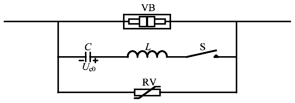
[0036] refer to Figure 7 As shown, the present invention discloses a main circuit topology of a medium voltage DC vacuum circuit breaker, including a vacuum circuit breaker VB 1 and vacuum circuit breaker VB 2 The main current path is composed of the commutation capacitor C, the auxiliary switch S and the commutation inductance L, and the commutation breaking circuit is composed of the auxiliary inductance L a and auxiliary capacitor C a Auxiliary breaking circuit composed of and energy absorbing circuit composed of piezoresistor RV.

[0037] The commutation capacitor C, the auxiliary switch S and the commutation inductance L are connected in series in sequence, and the commutation capacitor C is pre-charged U c0 , the main current path, the commutation breaking circuit and the energy absorbing circuit are connected in parallel, and the auxiliary breaking circuit is connected with the vacuum circuit breaker VB 1 connected in parallel with each other, the vacuum circuit br...

Embodiment 2

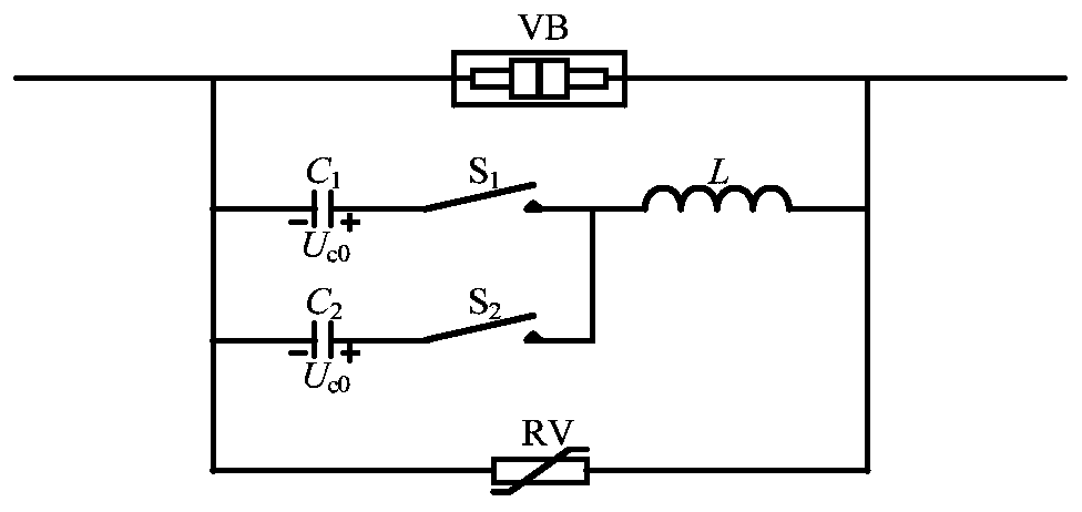
[0040] refer to Figure 8 As shown, in the normal working stage of the DC system, the vacuum circuit breaker VB 1 and vacuum circuit breaker VB 2 Closed, conducts load current. If it is necessary to break the normal load current, the breaking process is as follows:

[0041] 1) Vacuum circuit breaker VB 1 First break the arc;

[0042] 2) Then turn on the auxiliary switch S in the commutation breaking circuit, so that the commutation capacitor C passes through the auxiliary switch S, commutation inductance L, VB 2 and VB 1 The loop discharge formed by the arc gap, the generated pulse discharge current forces VB 1 The current quickly crosses zero and extinguishes the arc;

[0043] 3) Thereafter, the auxiliary inductance L a , Auxiliary capacitor C a with VB 2 Work in series and form a new second-order discharge circuit with the commutation breaking circuit, where the capacitance is equivalent to C a In series with C, the inductance is equivalent to L a and L in series...

Embodiment 3

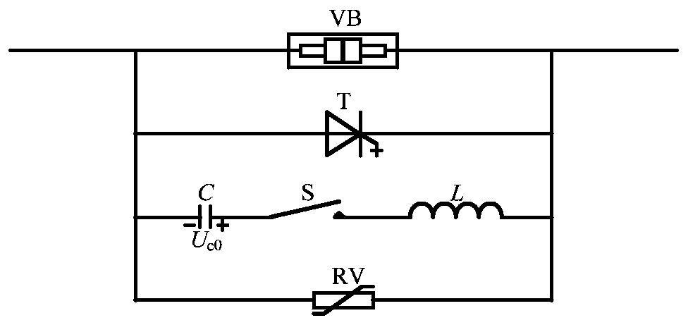
[0049] refer to Figure 9 As shown, after a short-circuit fault occurs in the DC system, the breaking process is as follows:

[0050] 1) First, the vacuum breaker VB 1 and vacuum circuit breaker VB 2 Simultaneously breaking and generating arc;

[0051] 2) Then, turn on the auxiliary switch S in the commutation breaking circuit, so that the commutation capacitor C passes through the auxiliary switch S, commutation inductance L and VB 1 , VB 2 The loop discharge formed by the arc gap, the generated pulse discharge current forces VB 1 -VB 2 The series branch current crosses zero at the same time and extinguishes the arc;

[0052] 3) If VB 1 and VB 2 Reliable arc extinguishing or only VB 2 If the arc is extinguished reliably, there is no current path in the auxiliary breaking circuit, which will not have any impact on the subsequent breaking process. Then the commutation breaking circuit is connected to the DC system to work, and C is reversely charged under the action of...


PUM


Abstract

The invention discloses a medium voltage DC vacuum circuit breaker main circuit topology, which comprises a main current path formed by serial connection of vacuum circuit breakers VB1 and VB2, a commutation breaking circuit formed by serial connection of a commutation capacitor C, an auxiliary switch S and a commutation inductor L, an auxiliary breaking circuit formed by serial connection of an auxiliary inductor La and an auxiliary capacitor Ca and an energy absorbing circuit formed by a varistor RV, wherein the main current path, the commutation breaking circuit and the energy absorbing circuit are connected in parallel; and the auxiliary breaking circuit and the vacuum circuit breaker VB1 are connected in parallel. The invention also discloses a commutation breaking method. In the caseof small current of a breaking DC system load, the vacuum circuit breakers VB1 and VB2 operate in sequence; and in the case of high current of fault of the breaking DC system, the vacuum circuit breakers VB1 and VB2 operate simultaneously. The medium voltage DC vacuum circuit breaker main circuit topology and the breaking method thereof have the characteristics of a reliable high current breakingprocess, quick small current breaking process and the like, and are suitable for a medium voltage DC high current system, and certain advantages are achieved in aspects of the device shape, the volume and the cost.

Description

technical field [0001] The invention belongs to the technical field of power system fault protection, and in particular relates to a main circuit topology of a medium-voltage DC vacuum circuit breaker and a breaking method thereof. Background technique [0002] The DC vacuum circuit breaker based on the active forced commutation technology, through the reverse high-frequency current provided by the discharge of the pre-storage capacitor C in the LC commutation circuit, makes the DC short-circuit current in the vacuum circuit breaker VB generate a zero-crossing point, and finally Arc cut off. It has high breaking capacity, relatively simple circuit structure, and relatively mature related technologies, which is an effective technical way to solve medium-voltage DC high-current breaking. The basic main circuit scheme as figure 1 shown. [0003] Usually in the medium-voltage DC power system, the DC circuit breaker not only needs to quickly break and isolate the short-circuit...

Claims


Application Information

Patent Timeline
Patent Type & Authority Applications(China)
IPC IPC(8): H02H7/26
CPCH02H7/268
Inventor 彭振东任志刚李博沙新乐邹顺李杰杨晨光
Owner WUHAN MARINE ELECTRIC PROPULSION RES INST CHINA SHIPBUILDING IND CORP NO 712 INST
Why Eureka
Try Eureka