Production device for super-huge type new energy battery box body

A production device and new energy technology, which is applied in the direction of liquid injection device, injection device, battery pack parts, etc., can solve the problems of troublesome clamping and low processing efficiency, so as to improve efficiency, improve processing efficiency, and clamp operation quick and easy effect

Inactive Publication Date: 2019-02-22
东莞市益合康五金压铸制品有限公司
View PDF0 Cites 18 Cited by
  • Summary
  • Abstract
  • Description
  • Claims
  • Application Information

AI Technical Summary

Problems solved by technology

[0004] The purpose of the present invention is to solve the problems in the prior art that the machining and spraying need to be operated separately, the clamping is troublesome, and the processing efficiency is low, and a production device for an extra-large new energy battery box is proposed.

Method used


Image

  • Production device for super-huge type new energy battery box body
  • Production device for super-huge type new energy battery box body
  • Production device for super-huge type new energy battery box body

Examples


Embodiment 1

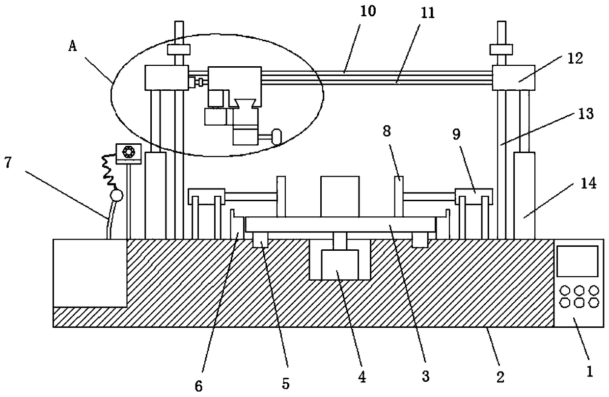
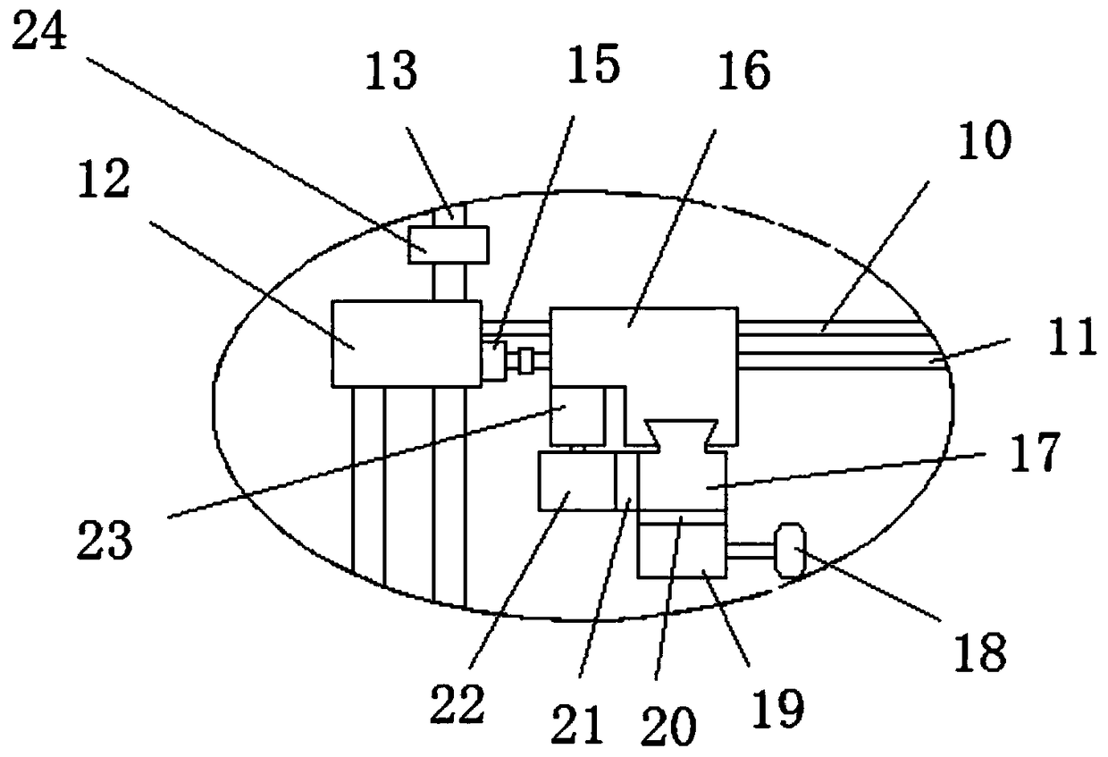
[0030] refer to figure 1 , image 3 , Figure 4 , Figure 5 , Image 6 , Figure 7 , a production device for an extra-large new energy battery box, including a base 2, the top of the base 2 is provided with an installation groove and a first chute, the first chute is a ring structure, and the first chute is located outside the installation groove, A first motor 4 is installed inside the installation groove, and a turntable 3 is installed on the output shaft of the first motor 4. The bottom of the turntable 3 is fixed with an annular first slider 5, and the first slider 5 is slidably installed on the top of the base 2. Inside the first chute;

[0031] The top of base 2 is equipped with support base 6, the first cylinder 9, the second cylinder 14, the second slide bar 13 and painting device 7, support base 6 is provided with four groups, and the top of support base 6 offers notch, the first Cylinder 9 is provided with four groups, and the end of the piston rod of first cyl...

Embodiment 2

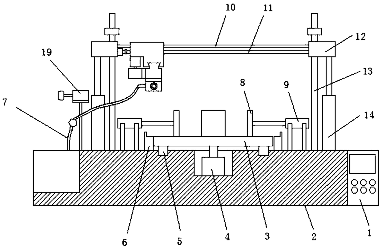
[0035] refer to figure 2 , image 3 , Figure 4 , Figure 5 , Image 6 , Figure 7, a production device for an extra-large new energy battery box, including a base 2, the top of the base 2 is provided with an installation groove and a first chute, the first chute is a ring structure, and the first chute is located outside the installation groove, A first motor 4 is installed inside the installation groove, and a turntable 3 is installed on the output shaft of the first motor 4. The bottom of the turntable 3 is fixed with an annular first slider 5, and the first slider 5 is slidably installed on the top of the base 2. Inside the first chute;

[0036] The top of base 2 is equipped with support base 6, the first cylinder 9, the second cylinder 14, the second slide bar 13 and painting device 7, support base 6 is provided with four groups, and the top of support base 6 offers notch, the first Cylinder 9 is provided with four groups, and the end of the piston rod of first cyl...


PUM


Abstract

The invention belongs to the technical field of new energy battery box bodies, and particularly relates to a production device for a super-huge type new energy battery box body. The production deviceaims at solving the problems that in existing machining devices, machining and spraying need to be separately operated, clamping is troublesome, and the machining efficiency is low. According to the scheme, the production device comprises a base, a mounting groove and a first sliding groove are formed in the top of the base, the first sliding groove is of an annular structure, the first sliding groove is located outside the mounting groove, a first motor is installed inside the mounting groove, a rotating disc is arranged on an output shaft of the first motor, an annular first sliding block isfixed at the bottom of the rotating disc, the first sliding block is arranged in the first sliding groove in the top of the base in a sliding mode, and the top of the base is provided with supportingseats, first air cylinders, second air cylinders, second sliding rods and a paint spraying device. According to the production device, through the movement in the X-axis direction, the Y-axis direction and the Z-axis direction, and then through the rotation of the rotating disc, machining or spraying operation can be carried out on any position of the side edge of the battery box body, so that the operation is quite simple.

Description

technical field [0001] The invention relates to the technical field of new energy battery boxes, in particular to a production device for extra-large new energy battery boxes. Background technique [0002] The types of battery boxes are mainly distinguished by the specifications, quantities and placement of batteries. Generally, there are three types of discrete type, horizontal type, and hand-operated type, and the number of storage batteries is also different. (1) Vertical type: The batteries in the battery box are placed vertically, and the batteries can be vertically arranged side by side or in series. The vertical battery box is characterized by occupying less area on the bottom plate of the product, and is suitable for products with a small bottom area. . (2) Horizontal type: The batteries of the battery box are placed horizontally, and the batteries can also be placed horizontally side by side or in series. The horizontal battery box is characterized by occupying a ...

Claims


Application Information

Patent Timeline
Patent Type & Authority Applications(China)
IPC IPC(8): B05B9/04B05B13/02B05B13/04H01M2/10H01M50/20
CPCB05B9/0403B05B13/0228B05B13/0285B05B13/0442H01M50/20Y02E60/10
Inventor 张英文
Owner 东莞市益合康五金压铸制品有限公司
Why Eureka
Try Eureka