
Thread-rolling machine capable of preventing sweeps from leaving on thread-rolling plates

The technology of thread rolling plate and thread rolling machine is applied in the field of thread rolling machine, which can solve the problems of insufficient smoothness of screw teeth, reduce bolt quality, screw influence, etc., and achieve the effect of avoiding secondary influence and improving product production quality.

Inactive Publication Date: 2019-02-22
嘉兴驰盛精密五金科技股份有限公司
View PDF13 Cites 1 Cited by
  • Summary
  • Abstract
  • Description
  • Claims
  • Application Information

AI Technical Summary

Problems solved by technology

The patent No. CN201520589255.6 is an automatic cycle thread rolling machine that can complete automatic feeding. During the feeding process, it avoids the problems of complicated operation and safety for workers, and the effect of thread rolling is good. However, currently in the process of bolt processing, Excess waste will be produced on the thread rolling board, which will affect the processing effect of the bolts to a certain extent and reduce the quality of the bolts; at the same time, in the thread rolling process, in order to reduce the local high temperature and prolong the life of the thread rolling board, it is necessary to spray The coolant cools down the workpiece and thread rolling board
[0003] However, although the spraying coolant cools down the thread rolling board, the cooling liquid is sprayed downward from the upper part, that is, it is perpendicular to the extending direction of the tooth lines on the thread rolling board, so it cannot wash away the waste chips, and some waste chips still remain on the thread rolling board. On the thread board, it will affect the screw that is re-rolled, so that the thread on the surface of the screw is not smooth enough or even misplaced

Method used


Image

  • Thread-rolling machine capable of preventing sweeps from leaving on thread-rolling plates
  • Thread-rolling machine capable of preventing sweeps from leaving on thread-rolling plates

Examples


Embodiment Construction

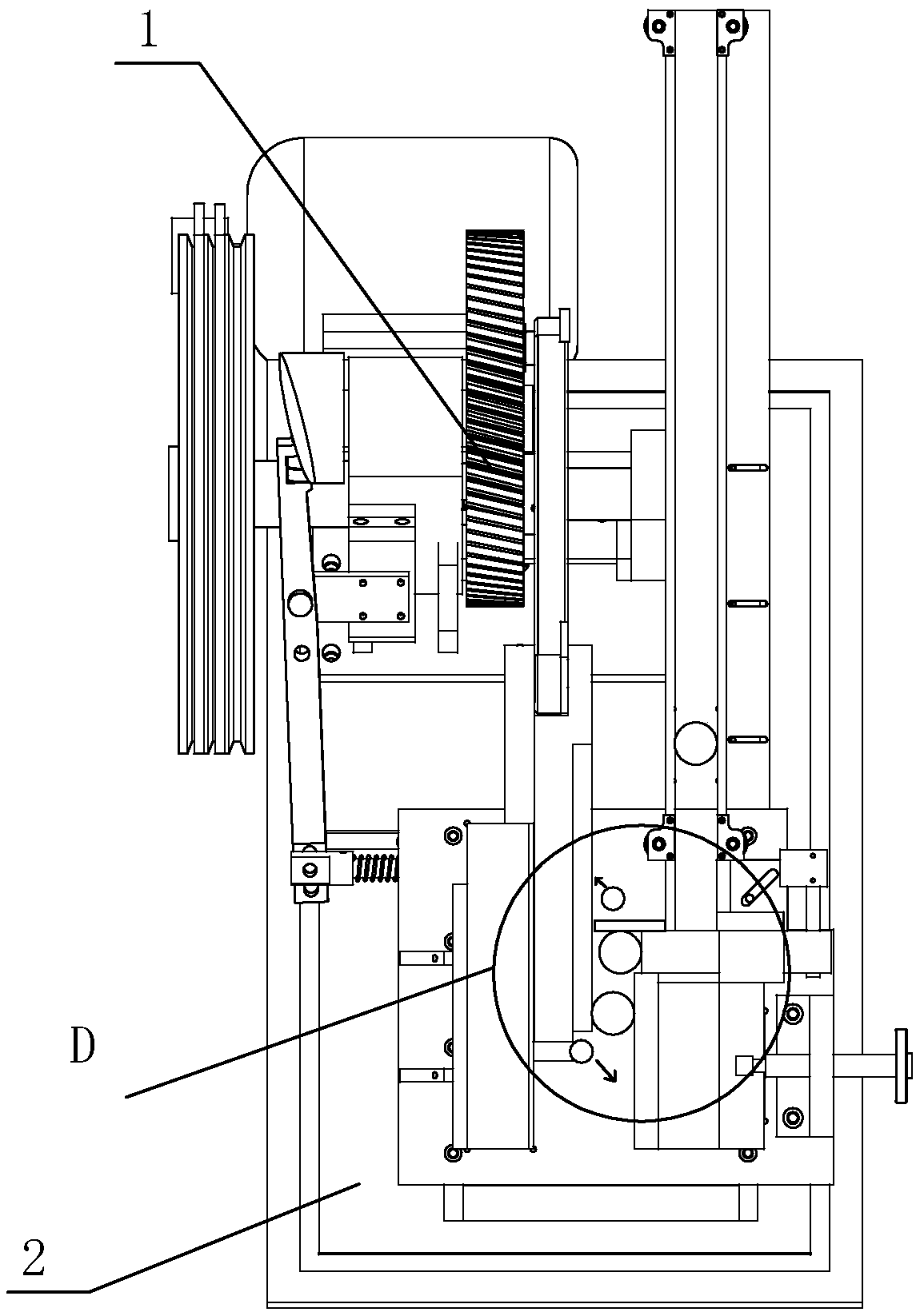
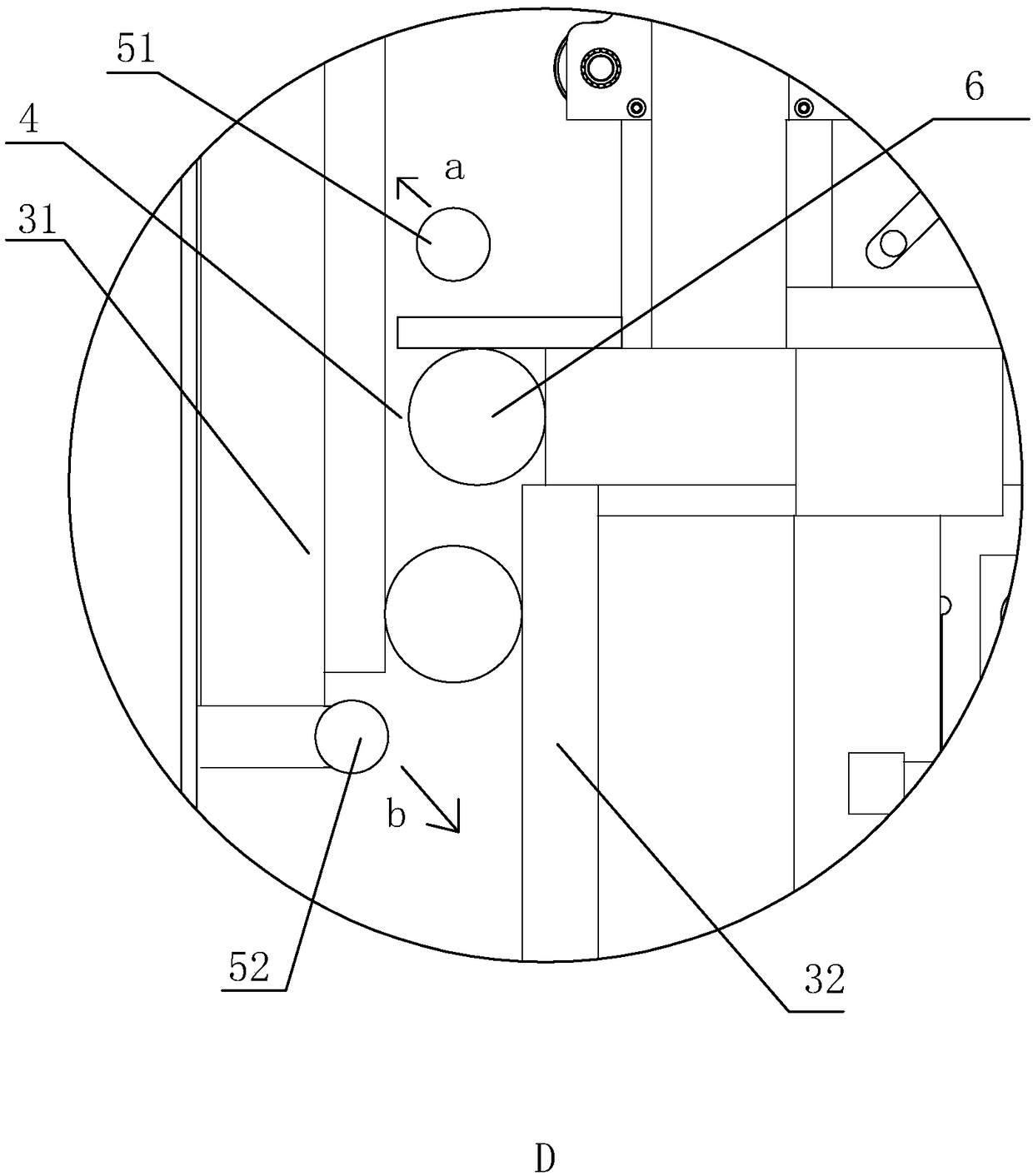
[0011] refer to figure 1 and figure 2 The embodiment of the thread rolling machine of the present invention that prevents waste from the thread rolling plate will be further described.

[0012] A thread-rolling machine for preventing waste left over by the thread-rolling plate, comprising a frame 2, on which a thread-rolling plate is arranged, and the thread-rolling plate includes a fixed plate 32 and a moving plate 31, and the two ends of the fixed plate 32 are respectively It is the inlet 4 and the outlet of the screw, the first chip removal nozzle 51 is provided on the frame 2 corresponding to the inlet 4, and the second chip removal nozzle 52 is arranged on the end of the moving plate 31 corresponding to the outlet. The axis of the first chip removal nozzle 51 and the second chip removal nozzle 52 is the same as the axis of the screw, and the first chip removal nozzle 51 and the second chip removal nozzle 52 are all provided with nozzles. The spout of the chip removal n...


PUM


Abstract

The invention discloses a thread-rolling machine capable of preventing sweeps from leaving on thread-rolling plates. The thread-rolling machine comprises a rack, the rack is provided with the fixed thread-rolling plate and the movable thread-rolling plate, the two ends of the fixed thread-rolling plate are an inlet and an outlet for screws correspondingly, a first sweep removing spraying pipe is arranged at the position, corresponding to the inlet, of the rack, a second sweep removing spraying pipe is arranged at the end, corresponding to the outlet, of the movable thread-rolling plate, the axes of the first sweep removing spraying pipe and the second sweep removing spraying pipe are the same as the axes of the screws, the first sweep removing spraying pipe and the second sweep removing spraying pipe are provided with spraying openings, the spraying opening of the first sweep removing spraying pipe faces the movable thread-rolling plate, and the spraying opening of the second sweep removing spraying pipe faces the fixed thread-rolling plate. The thread-rolling machine can remove the sweeps on the thread-rolling plates, cannot affect the screws, ensures the thread rolling quality ofthe screws, and has the cooling effect.

Description

technical field [0001] The invention belongs to the field of thread rolling machines, and more specifically relates to a thread rolling machine for preventing waste left by a thread rolling plate. Background technique [0002] Thread rolling machine is an equipment specialized in the production of screws. The patent No. CN201520589255.6 is an automatic cycle thread rolling machine that can complete automatic feeding. During the feeding process, it avoids the problems of complicated operation and safety for workers, and the effect of thread rolling is good. However, currently in the process of bolt processing, Excess waste will be produced on the thread rolling board, which will affect the processing effect of the bolts to a certain extent and reduce the quality of the bolts; at the same time, in the thread rolling process, in order to reduce the local high temperature and prolong the life of the thread rolling board, it is necessary to spray The coolant cools down the workp...

Claims


Application Information

Patent Timeline
Patent Type & Authority Applications(China)
IPC IPC(8): B21H3/06
CPCB21H3/06
Inventor 马永明
Owner 嘉兴驰盛精密五金科技股份有限公司
Learn More