
Silk screen printing screen frame system capable of being rapidly positioned

A technology of screen printing and screen frame, which is applied to screen printing machines, printing machines, printing machines, etc. It can solve the problems of poor calibration accuracy and long calibration time, and achieve the effects of fast calibration, short calibration time and high positioning accuracy

Active Publication Date: 2019-02-22
网都河北科技服务有限公司
View PDF7 Cites 4 Cited by
  • Summary
  • Abstract
  • Description
  • Claims
  • Application Information

AI Technical Summary

Problems solved by technology

[0004] The purpose of the present invention is to overcome the defects and problems of long calibration time and poor calibration accuracy existing in the prior art, and provide a screen printing screen frame system with short calibration time and good calibration accuracy that can be quickly positioned

Method used


Image

  • Silk screen printing screen frame system capable of being rapidly positioned
  • Silk screen printing screen frame system capable of being rapidly positioned
  • Silk screen printing screen frame system capable of being rapidly positioned

Examples


Embodiment 1

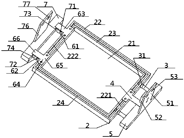
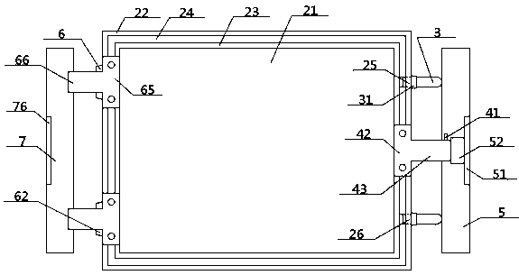
[0045] see Figure 1 to Figure 6 , a screen printing screen frame system that can be quickly positioned, including a screen frame 2 for screen printing; A concentric outer frame 22 is sleeved, and the bottom surfaces of the outer frame 22 and the inner frame 23 are all connected with the top surface of the frame bottom surface 21, and a concentric inter-frame groove 24 is sandwiched between the outer frame 22 and the inner frame 23, and the outer frame 22 Open the upper screw hole 25, the lower screw hole 26 on the right frame bar 221 of the upper screw hole 25, and the lower screw hole 26 is respectively provided with a distance-adjusting screw 3, and the inner end of the distance-adjusting screw 3 extends to the groove 24 between the frames Inside, the outer end of the pitch-adjusting screw 3 passes through the upper screw hole 25 or the lower screw hole 26 and extends to the outside of the outer frame 22, and the pitch-adjusting screw 3 is provided with a pitch-adjusting nu...

Embodiment 2

[0047] Basic content is the same as embodiment 1, the difference is:

[0048] The top surface of the right fixed plate 5 is vertically connected with the bottom edge of the right vertical plate 51, and the inner side of the right vertical plate 51 is provided with a downward pressure cylinder 52, and the output end of the downward pressure cylinder 52 is located at the top of the right fixed plate 5. Directly above the surface, the projection of the output end of the downward pressure cylinder 52 on the top surface of the right fixed plate 5 intersects with the horizontal extension line of the positioning plate 4 outer ends. The positioning plate 4 is a T-shaped structure, including positioning vertical bars 42 and positioning horizontal bars 43, the bottom surface of the positioning vertical bars 42 is connected with the top surface of the screen frame 2, and the right side of the positioning vertical bars 42 is connected with the positioning horizontal bar. The inner end of ...

Embodiment 3

[0050] Basic content is the same as embodiment 1, the difference is:

[0051] The left fixing part 6 includes an upper left inserting block 61 and a lower left inserting block 62 arranged up and down along the left frame bar 222, and an upper left groove 71 and a lower left groove 72 arranged up and down are arranged on the inner surface of the left fixing plate 7. To carry out the corresponding insertion fit with the upper left inserting block 61 and the lower left inserting block 62 . The inner surface of the left fixed plate 7 is connected with the inner ends of the upper left telescopic part 73 and the lower left telescopic part 74, the outer end of the upper left telescopic part 73 is connected with the left side part of the upper left groove 71, and the outer part of the lower left telescopic part 74 The end is connected with the left side of the lower left groove 72, and the upper left groove 71 and the right side of the lower left groove 72 are provided with notches 75...


PUM


Abstract

The invention provides a silk screen printing screen frame system capable of being rapidly positioned. A screen frame in the system comprises a frame bottom face, an outer frame and an inner frame. The outer frame and the inner frame are connected with the top face of the frame bottom face and sleeved inside and outside. A concentric inter-frame groove is sandwiched between the outer frame and theinner frame, the inner ends of distance adjusting screws arranged in screw holes formed in the right side of the outer frame stretch into the inter-frame groove, the outer ends of the distance adjusting screws penetrate through the screw holes and then stretch out of the outer frame, the portions, located outside the outer frame, of the distance adjusting screws are sleeved with distance adjusting nuts, the portion, sandwiched between the upper screw hole and the lower screw hole, of the screen frame is connected with the inner end of a positioning plate, a right fixing plate right opposite to the outer ends of the distance adjusting screws is arranged on the right side of the outer frame, a positioning pin in limiting cooperation with the positioning plate is perpendicularly connected tothe top face of the right fixing plate, a left frame strip of the outer frame is connected with the inner end of a left fixing part, and the outer end of the left fixing part is right opposite to theinner side face of a left fixing plate. By means of the design, the silk screen printing screen frame system is short in calibration time, good in calibration precision, high in adjustability and high in stability.

Description

technical field [0001] The invention relates to a screen frame adjustment device, which belongs to the field of screen printing equipment, in particular to a screen printing screen frame system that can be quickly positioned, and is particularly suitable for shortening calibration time and improving calibration accuracy. Background technique [0002] In screen printing, it is required that the screen frame and the fabric below must be strictly aligned, otherwise, once a certain place is misaligned, it will damage the accuracy and quality of the printing, and even cause the entire piece of fabric to be scrapped. However, in practical applications, as the printing operation goes on for a long time, the screen frame will inevitably move. At this time, the screen frame needs to be recalibrated. However, in the prior art, the calibration of the screen frame is not only complex in structure and requires a long operation time, but also the accuracy cannot be guaranteed, the calibra...

Claims


Application Information

Patent Timeline
Patent Type & Authority Applications(China)
IPC IPC(8): B41F15/36B41F15/14
CPCB41F15/14B41F15/36
Inventor 张智明段耀帅陈博雅赖梓龙徐巧梅顺齐肖人彬
Owner 网都河北科技服务有限公司
Learn More