
Steel rail wearing detecting device

A technology for detecting device and rail wear, which is applied in the directions of measuring device, optical device, transportation and packaging, etc., which can solve problems such as caliper wear, high worker ability requirements, and decreased measurement accuracy.

Active Publication Date: 2019-02-22
EAST CHINA JIAOTONG UNIVERSITY
View PDF7 Cites 16 Cited by
  • Summary
  • Abstract
  • Description
  • Claims
  • Application Information

AI Technical Summary

Problems solved by technology

[0005] In the prior art, the steel rail is usually tested by purely mechanical caliper measurement method. The measuring instrument of pure mechanical caliper measurement method is configured according to different rail models. The measuring instrument is clamped to the bottom of the rail, and then the top and side pointers of the instrument are pressed down. Hold the surface of the rail and read the measurement data at this time. However, the measuring instrument of the pure mechanical caliper measurement method has high requirements on the worker's ability, heavy workload, low work efficiency, and is greatly affected by human factors. Long-term use will cause the caliper to wear out. , resulting in a decrease in measurement accuracy and the inability to continuously detect the degree of wear of the entire rail

Method used


Image

  • Steel rail wearing detecting device
  • Steel rail wearing detecting device
  • Steel rail wearing detecting device

Examples


Embodiment Construction

[0038] The present invention will be described in further detail below in conjunction with the embodiments and with reference to the accompanying drawings.

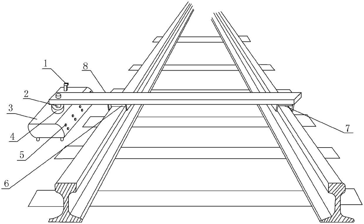
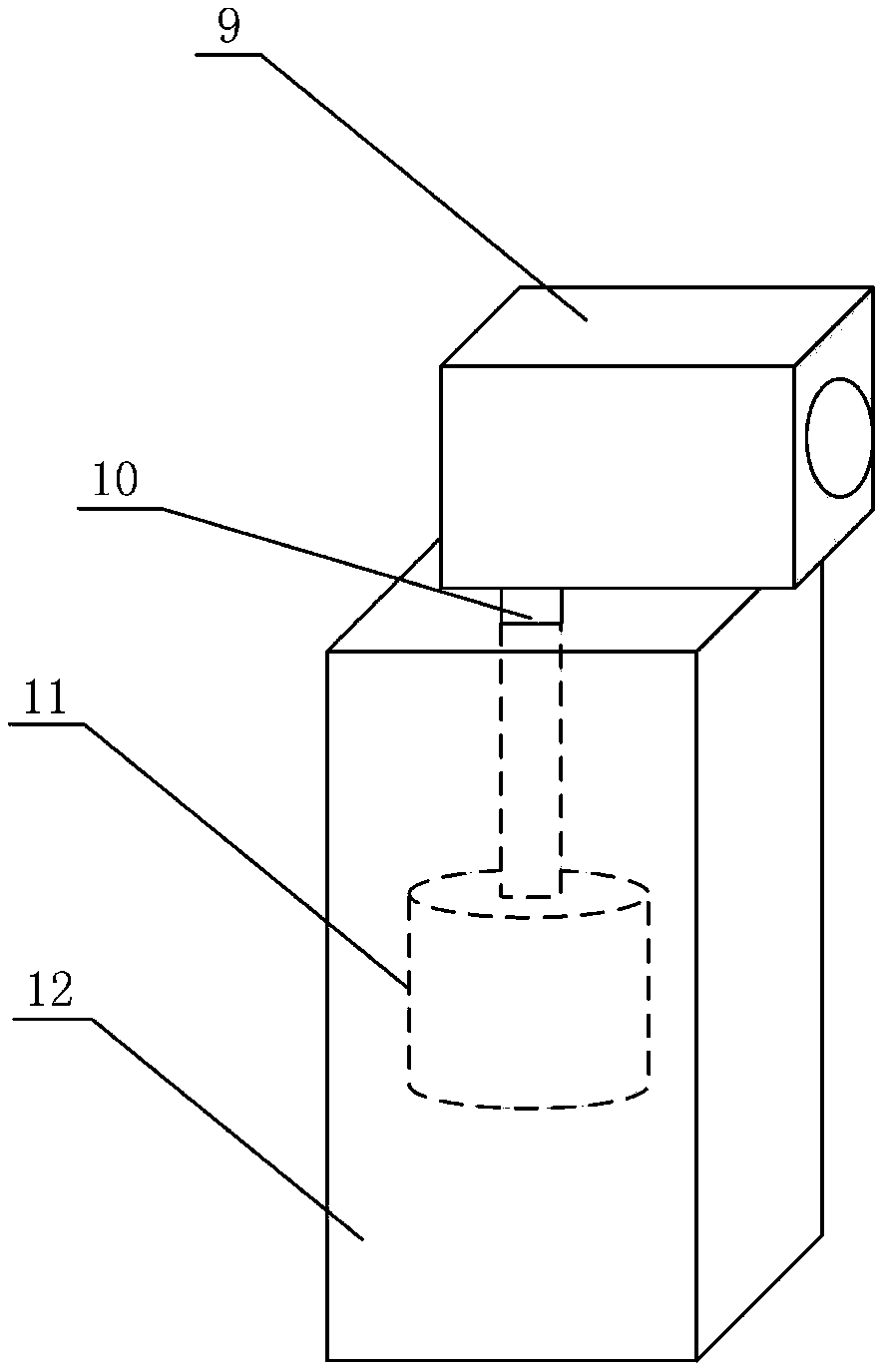
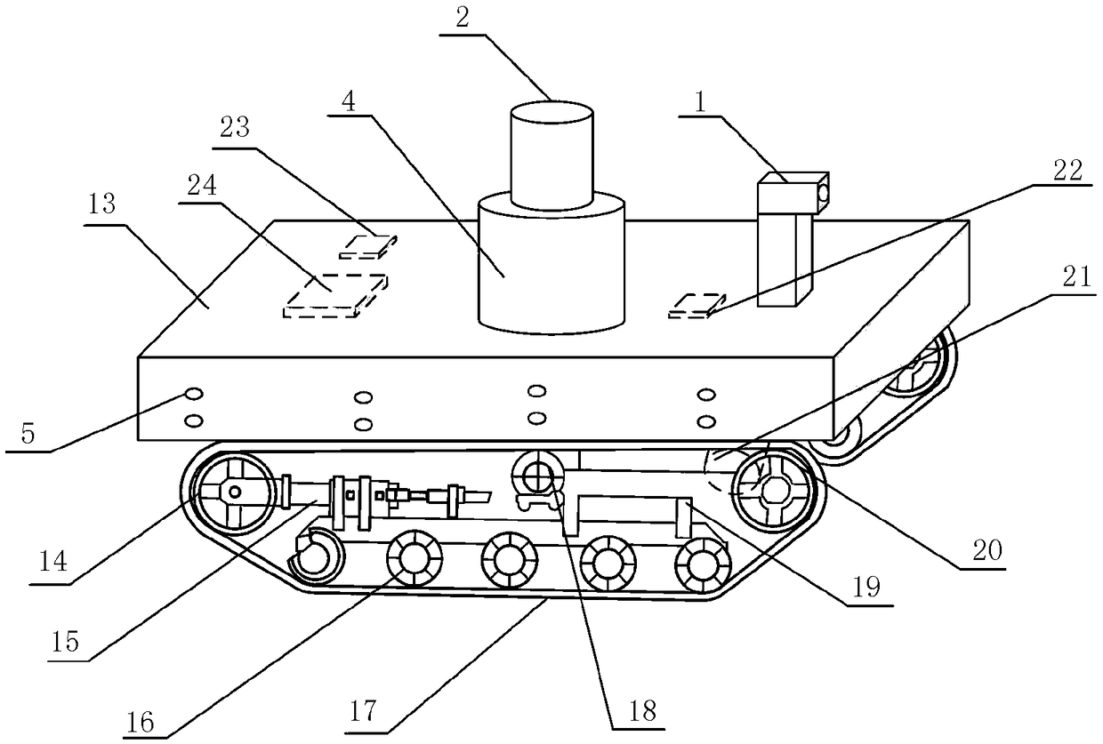
[0039] see Figures 1 to 10 , shows a rail wear detection device in the present invention, including an image acquisition device 1, a first telescopic motor 2, a traveling device 3, a servo motor 4, an ultrasonic rangefinder 5, a left wear detector 6, a right wear detection Instrument 7, crossbar 8.

[0040] like figure 1 As shown, the walking device 3 is used to move the crossbar 8, and moves along the outer side of the track with the assistance of the image acquisition device 1 and the ultrasonic range finder 5, so that the left wear detector 6 and the right wear detector 7 To detect along the rail, the image acquisition device 1 and the servo motor 4 are installed on the top of the traveling device 3, the image acquisition device 1 is used to guide the traveling device 3 to move forward, and at the same time guide th...


PUM


Abstract

The invention discloses a steel rail wearing detecting device comprising an image collecting device, a first telescopic motor, a walking device, a servo motor, an ultrasonic range finder, a left wearing detector, a right wearing detector and a cross bar. The detecting device walks along the rail by using the walking device, wherein the distance between the walking device and the outer side of thesteel rail is consistent all the same. The left wearing detector and the right wearing detector are installed at the walking device to carry out synchronous wearing detection and rail distance detection of the two steel rails at the same track. The image collecting device guides the walking device to move forward and guides the cross bar to stretch the left wearing detector and the right wearing detector to the steel rails for detection. A GSM module transmits departure information of a dispatch center to the walking device; and when a train enters the zone, the walking device rotates the cross bar to the outer side of the track, thereby preventing the cross bar from affecting driving of the train.

Description

technical field [0001] The invention relates to the field of rail detection, in particular to a rail wear detection device. Background technique [0002] Rails are components of railway tracks that are primarily used to guide the wheels of rolling stock, to withstand the pressure on the wheels, and to transmit this force to the sleepers. With the rapid development of railways, heavy-duty trains and high-speed trains are becoming more and more important in the railway transportation industry, and the existence of heavy-duty trains and high-speed trains makes the rails wear and deform. When the rails used on the line reach If the degree of serious injury is exceeded, driving safety will be affected. [0003] During the use of rails, rail wear will occur. Rail wear mainly refers to the side wear and wave wear of the rail on the small radius curve. As for vertical wear, it is generally normal and increases with the increase of axle load and total passing weight. Among them: ...

Claims


Application Information

Patent Timeline
Patent Type & Authority Applications(China)
IPC IPC(8): G01B11/02G01B11/00B61K9/08
CPCB61K9/08G01B11/00G01B11/02
Inventor 朱海燕曹文琴朱志和王超文
Owner EAST CHINA JIAOTONG UNIVERSITY
Learn More