Radio frequency filter with periodic structure

A radio frequency filter and periodic structure technology, applied in the field of filters, can solve problems such as miniaturization, integration, small frequency range, and filter failure, and achieve simple structure, increased stop band range, and stop band The effect of increased decay rate

Active Publication Date: 2019-02-22
SUN YAT SEN UNIV
View PDF3 Cites 0 Cited by
  • Summary
  • Abstract
  • Description
  • Claims
  • Application Information

AI Technical Summary

Problems solved by technology

[0003] At present, the LC loop is still widely used in the design of filters, and the frequency range is small, and it is easy to cause the filter to fail if it exceeds a certain fre

Method used


Image

  • Radio frequency filter with periodic structure
  • Radio frequency filter with periodic structure
  • Radio frequency filter with periodic structure

Examples


Embodiment Construction

[0026] Below in conjunction with accompanying drawing, the present invention will be further described.

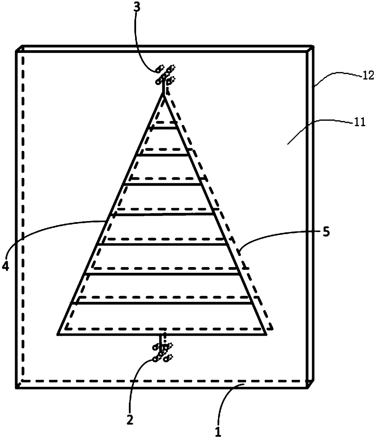
[0027] figure 1 is a schematic diagram of the structure of an RF filter with a periodic structure. Such as figure 1 As shown, the radio frequency filter with a periodic structure includes a substrate 1 , a conductor pattern, a first connection terminal 2 and a second connection terminal 3 . The substrate 1 is generally in the shape of a flat plate, including a first side 11 and a second side 12 opposite to each other, and is made of epoxy glass cloth laminated board (FR-4).

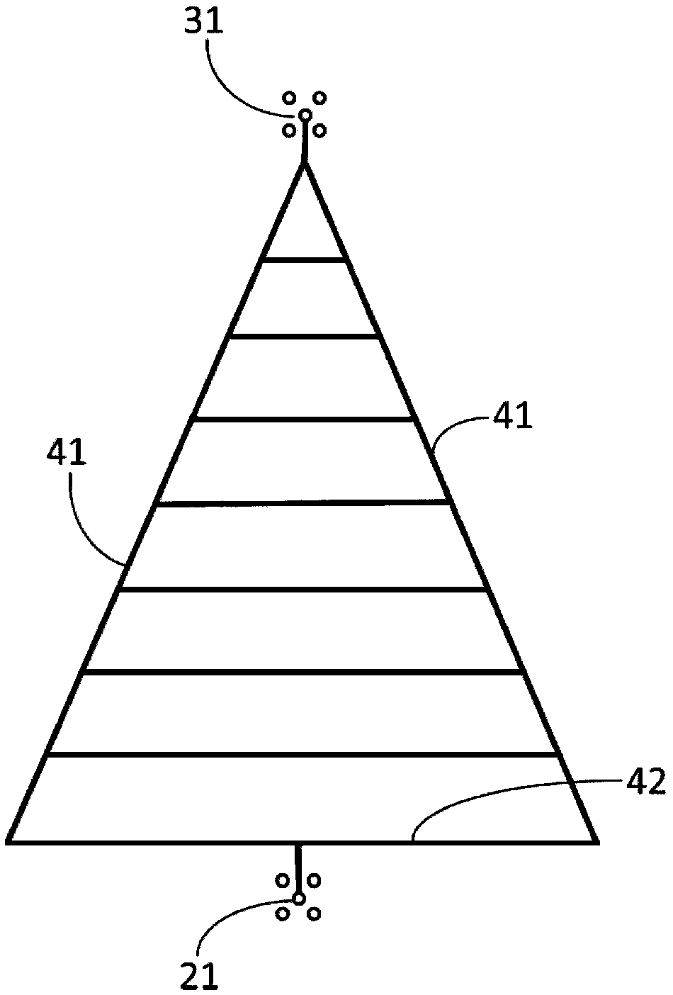
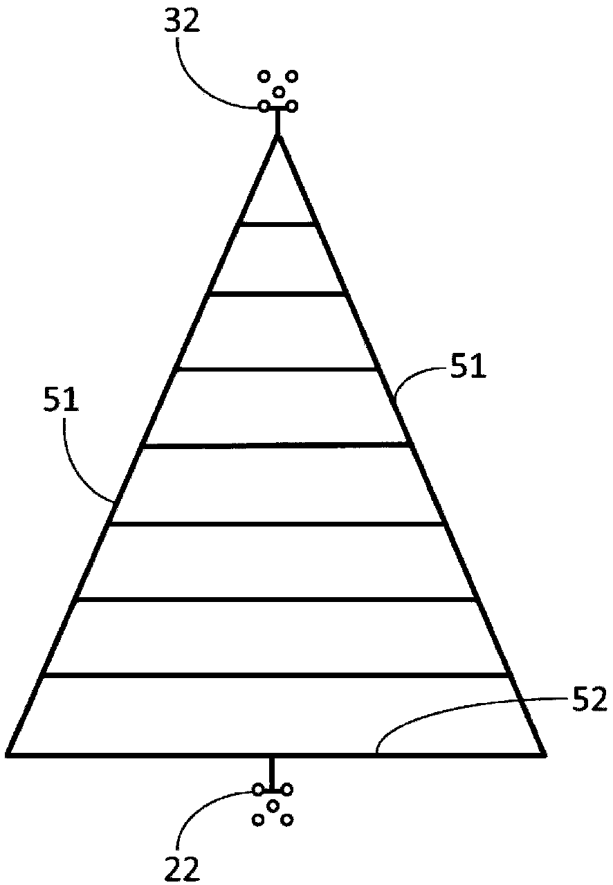
[0028] The conductor patterns are symmetrically arranged on the first side 11 and the second side 12 of the substrate 1 . The following combination figure 2 and image 3 The structures of the conductor patterns on the first side 11 and the second side 12 are described respectively.

[0029] figure 2 is a schematic diagram of a conductor pattern located on the first side 11 of a radio frequenc...


PUM


Abstract

The present invention discloses a radio frequency filter having a periodic structure. The radio frequency filter comprises: a substrate including opposite first and second side surfaces; conductor patterns symmetrically disposed on the first side surface and the second side surface of the substrate, wherein each conductor pattern includes a plurality of connecting rails and two intersecting connecting wires, two ends of the connecting rails are connected to the connecting wires, and equidistantly disposed between the connecting wires in parallel, so that the length of the connecting rails is reduced equidistantly in the direction near the intersection of the connecting wires. According to the radio frequency filter with the periodic structure, mutually symmetric conductor patterns are produced on the substrate, each conductor pattern comprises a periodic structure formed by the connecting wires and the connecting rails which are equidistantly arranged and having an increasing length. According to the Bloch's theorem, the periodic structure can create a Brillouin zone to form a plurality of discrete stop bands.

Description

technical field [0001] The invention belongs to the technical field of filters, in particular to a periodic structure and a radio frequency filter. Background technique [0002] Filters are an integral part of RF systems used to pass or reject specific frequency bands. Filters can be divided into low-pass filters (LPF), high-pass filters (HPF), band-pass filters (BPF), and band-rejection filters (BRF) according to the frequency range of their action. Now that we are gradually entering the era of 5G communication, the application of millimeter wave technology is more extensive, so the new radio frequency filter acting in a higher frequency range is playing an increasingly important role. [0003] At present, LC loops are still widely used in the design of filters, and the frequency range is small. Exceeding a certain frequency will easily lead to filter failure; and the structure is complex, requiring multiple sets of LC loops. The size of these passive devices is not small...

Claims


Application Information

Patent Timeline
IPC IPC(8): H01P1/203
Inventor 粟涛王策兴刘健陈弟虎
Owner SUN YAT SEN UNIV
Why Eureka
Try Eureka