Analog amplification vacuum tube

A vacuum tube, heat-releasing technology, used in amplifier types, low-frequency amplifiers, audio amplifiers, etc., can solve the problems of reduced manufacturing volume, difficult to obtain, difficult to use fluorescent display tubes, etc., to achieve the effect of improving the attenuation rate and suppressing the impact

Active Publication Date: 2020-08-18
NORITAKE CO LTD +1
View PDF7 Cites 0 Cited by
  • Summary
  • Abstract
  • Description
  • Claims
  • Application Information

AI Technical Summary

Problems solved by technology

However, there are problems such as a reduction in production volume, an increase in price, and difficulty in obtaining
On the other hand, as a kind of vacuum tube, the cheap and widespread fluorescent display tube is difficult to use for analog amplification.

Method used


Image

  • Analog amplification vacuum tube
  • Analog amplification vacuum tube
  • Analog amplification vacuum tube

Examples


Embodiment 1

[0032]

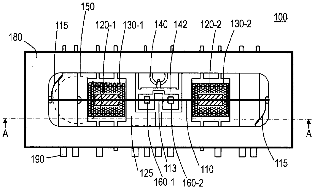
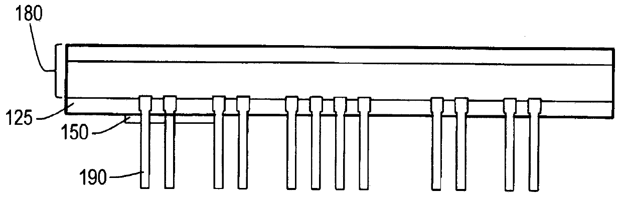
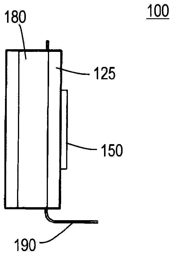
[0033] figure 1 A plan view showing a vacuum tube for analog amplification of the present invention, figure 2 represents the main view, image 3 represents a side view, Figure 4 express figure 1 Sectional view of line A-A. The vacuum tube 100 for analog amplification has: a linearly extending filament 110 that emits thermal electrons at a temperature higher than a predetermined value; 1, 160-2. Both the anodes 120-1 and 120-2 are formed on the same surface of the flat substrate (glass substrate 125). The filament 110 is arranged parallel to the planar substrate (glass substrate 125 ) at a position facing both the anodes 120 - 1 and 120 - 2 . Each of the grids 130-1, 130-2 is disposed on the anodes 120-1, 120-2 so as to face the anodes 120-1, 120-2 of the same group at a first predetermined distance and to have a second predetermined distance from the filament 110. 120-2 and the filament 110. The filament intermediate fixing part 113 which fixes the filamen...

Deformed example 1

[0049] Figure 14 A plan view of a vacuum tube for analog amplification showing a modified example, Figure 15 express Figure 14 Sectional view of the B-B line. The vacuum tube for analog amplification 200 is different from the vacuum tube for analog amplification 100 in that there is only one set of anode 120 , grid 130 , and anti-vibration unit 160 , the position of getter 140 and the method of fixing filament 110 . exist Figure 14 In , in order to easily understand the position of the anode 120, a part of the grid 130 is not described, but the grid 130 and Figure 9 same. In the vacuum tube 200 for analog amplification, since there is only one set of the anode 120 and the grid 130 , it is not necessary to limit the position of the getter 140 in order to adjust the characteristics. Therefore, the getter 140 is provided at the end of the analog amplification vacuum tube 200 in a state held by the getter support member 242 .

[0050] In the vacuum tube 200 for analog a...


PUM

PropertyMeasurementUnit
thicknessaaaaaaaaaa

Abstract

An analog amplification vacuum tube according to the present invention suppresses the influence of filament vibration on amplification characteristics. The analog amplification vacuum tube according to the present invention is provided with a filament, an anode, a grid, and a vibration-proof part. The filament is linearly laid, and emits thermoelectrons. The anode is disposed in parallel with thefilament. The grid is disposed, so as to oppose the anode, between the filament and the anode. The vibration-proof part has a thin film usable in a vacuum environment, and the thin film comes into contact with a part of the filament.

Description

technical field [0001] The present invention relates to a vacuum tube for analog amplification operating as an analog amplifier. Background technique [0002] There is a demand for vacuum tubes that can be used as analog amplifiers, and there are vacuum tubes that can be used as analog amplifiers. However, there are problems such as reduction in production volume, increase in price, and difficulty in obtaining them. On the other hand, as a type of vacuum tube, an inexpensive and widespread fluorescent display tube is difficult to use for analog amplification. The techniques of Patent Documents 1 and 2 have structures similar to inexpensive and readily available fluorescent display tubes, and are known as techniques that can provide vacuum tubes that can easily operate as analog amplifiers. [0003] prior art literature [0004] patent documents [0005] Patent Document 1: Japanese Patent Laid-Open No. 2016-134298 [0006] Patent Document 2: Japanese Patent Laid-Open No....

Claims


Application Information

Patent Timeline
Patent Type & Authority Applications(China)
IPC IPC(8): H01J19/12H01J19/42H01J21/22
CPCH01J19/12H01J19/42H01J21/22H03F1/33H03F3/181H03F2200/03
Inventor 龙田和典中尾刚启江崎智隆
Owner NORITAKE CO LTD
Why Eureka
Try Eureka