
Cleaning device with a motor-driven oscillating plate

A cleaning device and motor-driven technology, applied in manual floor scrubbing machines, floor leveling/polishing machines, machine parts, etc., can solve problems such as unbalanced force

Inactive Publication Date: 2019-02-26
VORWERK & CO INTERHOLDING GMBH
View PDF7 Cites 0 Cited by
  • Summary
  • Abstract
  • Description
  • Claims
  • Application Information

AI Technical Summary

Problems solved by technology

However, if an imbalance of forces occurs, the cleaning device drifts sideways

Method used


Image

  • Cleaning device with a motor-driven oscillating plate
  • Cleaning device with a motor-driven oscillating plate
  • Cleaning device with a motor-driven oscillating plate

Examples


Embodiment Construction

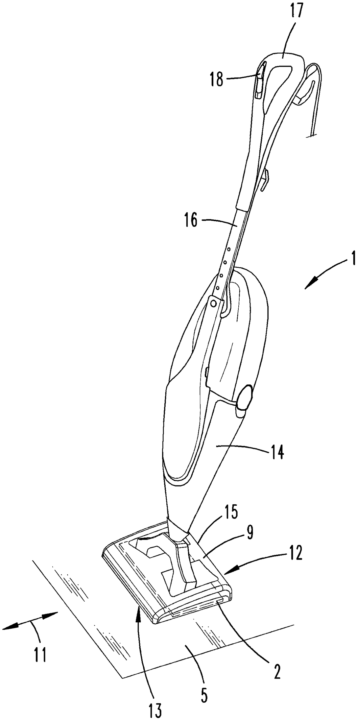
[0033] figure 1 Shown is a cleaning device 1 , which is here a hand-held wet cleaning device with a basic device 14 and an additional device 15 . The additional device 15 itself is a cleaning device 1 within the meaning of the invention. The basic device 14 has a handle 16 , which is designed to be telescopic, for example, so that the user of the cleaning device 1 can adapt the length of the handle 16 to his height. Also arranged on the handle 16 is a handle 17 on which the user can guide the cleaning device 1 during the usual cleaning operation, ie can move it over the surface to be cleaned with the cleaning plane 5 . During the wiping operation, the user generally guides the cleaning device 1 over the surface to be cleaned in opposite directions of movement, namely the main direction of movement 11 . Here, the user alternately moves the cleaning device 1 towards and away from him. Arranged on the handle 17 is a switch 18 which is used, for example, to switch the motor of ...


PUM


Abstract

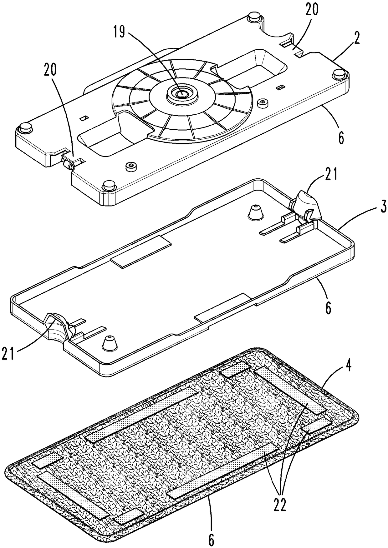
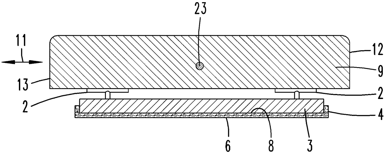
The invention relates to a cleaning device (1). The device comprises a housing (9), a motor-driven oscillating plate (2) and a carrier plate (3) capable of being connected to the oscillating plate (2)and used for receiving a cleaning element (4). The oscillating plate (2) can be driven during cleaning operation of the cleaning device (1) and is used for oscillating a cleaning surface (5) relativeto a surface to be cleaned. In order to be able to compensate or expediently cause a drift of the cleaning device (1), it is proposed here that the carrier plate (3) and / or the cleaning element (4) are configured in a wedge-shaped manner, wherein the carrier plate (3) and / or the active side (6) of the cleaning element (4) facing the cleaning surface (5) is oriented parallel to the cleaning surface (5) in the usual position of the cleaning device (1) for the cleaning operation.

Description

technical field [0001] The invention relates to a cleaning device with a housing, a motor-driven oscillating plate and a carrier plate connectable to the oscillating plate for receiving cleaning elements, wherein the oscillating plate can be driven during the cleaning operation of the cleaning device, For implementing an oscillation relative to the cleaning plane of the surface to be cleaned. [0002] Furthermore, the invention relates to a method for operating a cleaning device, wherein a motor-driven pivot plate and a carrier plate connected to the pivot plate are driven during the cleaning operation of the cleaning device in order to implement a cleaning plane relative to the surface to be cleaned swing, the carrier plate has cleaning elements arranged thereon. Background technique [0003] Cleaning devices of the aforementioned type are known in the prior art. The cleaning device can be, for example, a wet cleaning device. [0004] The cleaning device is used in parti...

Claims


Application Information

Patent Timeline
IPC IPC(8): A47L11/28A47L11/40
CPCA47L11/28A47L11/40A47L11/06A47L11/12
Inventor W.韦伯
Owner VORWERK & CO INTERHOLDING GMBH
Learn More