Container cap equipped with function for unfolding state

An open state, container cap technology, applied in the field of container caps with the function of maintaining the open state, can solve the problems of easy disconnection, loss of the cap body 16, and obstruction of users, etc., and achieve the expansion of the reclining angle without affecting the appearance Effect

Active Publication Date: 2019-02-26
成甫渊
7 Cites 4 Cited by

AI-Extracted Technical Summary

Problems solved by technology

[0020] However, extending the length of the support frame 32 cannot finally provide force for the support frame 32 to be close to the inner wall of the bottle mouth N of the container B and can only become the state of being hung up. Therefore, the lid main body 16 is opened from the opening of the container B. If the angle is less than 90°, it is troublesome for the user to take measures by hand so that the lid main body 16 is located at a position where it does not interfere with the opening of the container B.
[0021] In addition, in order to solve the above-mentioned problem, in prior art 3, a protruding portion that is locked corresponding to the locking convex portion C or the external thread M/S formed on the mouth N of the container B is formed at the position of t...

Abstract

The invention relates to a cap with stay-open function, including a tamper ring to be prevented from separation from a spout of a container, a cap body for screwing to an outer circumferential surfaceof the spout of the container, a hinge portion for interconnecting the cap body and the tamper ring over a circumferential portion of a cutout section defined by and between the cap body and the tamper ring, and bridges configured to connect the cap body and the tamper ring at intervals along the circumferential portion of the cutout section, and to be cut when the cap body is opened. The hinge portion has both side edges, which are respectively adjacent to the cutout section, deepen from an outer surface toward an inner surface of the cap body to form bending indents integrated with the capbody and the tamper ring, and to include a lower longitudinally central area extending downwardly to form a protrusion. The tamper ring has a longitudinally central area including a section set to form a slit, and to have an area corresponding to the projection with a space maintained and indented downwardly by a depth to form a recess.

Application Domain

Closure capsLids +2

Technology Topic

Engineering

Image

  • Container cap equipped with function for unfolding state
  • Container cap equipped with function for unfolding state
  • Container cap equipped with function for unfolding state

Examples

  • Experimental program(1)

Example Embodiment

[0042] The terms or vocabulary used in the description of the present invention and the scope of the claims should not be limitedly interpreted as ordinary or dictionary meanings, but should be based on the principle that the inventor can properly define the concept of the term in order to describe his own invention in the best way, Meanings and concepts that should be construed as conforming to the technical idea of ​​the present invention.
[0043] In addition, the embodiments described in the description of the present invention and the illustrated structures are only preferred embodiments of the present invention, and do not represent all technical ideas of the present invention. Therefore, it should be understood that the present invention can replace the Various equivalents and modified examples all fall within the scope of the claims of the present invention.
[0044] Moreover, when describing the present invention, the state of the vertically placed container, that is, the state where the mouth of the container is on the upper side, is used as a reference, and the expression inside refers to the central direction of the container interior or the position located in this direction at this height, The outer side refers to the direction opposite to the inner side or a site located in the direction.
[0045] Hereinafter, preferred embodiments of the present invention will be described in detail with reference to the accompanying drawings.
[0046] like Figure 5 to Figure 7 As shown, the container cap 40 with the function of maintaining an open state according to the present invention is the same as the prior art, including: a display ring 44, which is supported by the locking convex part C formed on the bottle mouth N of the container B to prevent it from coming off The cover main body 42 forms a screw joint structure with respect to the outer peripheral surface E/S of the bottle mouth N of the container B, and the lower side part is spaced apart from the upper side of the display ring 44 to form a cutout 52; the hinge part 56 is formed on the cover main body 42 and the display ring 44 in the preset partial section in the perimeter of the cutout portion 52, interconnecting the cover main body 42 and the display ring 44; The space between the cutouts 52 is widened by the opening of the cover main body 42, thereby being disconnected.
[0047] In the above structure, according to the hinge portion 56 of the present invention, its side edge portions in the width direction adjacent to the ends of the both side cutout portions 52 have a depth from the outer side to the inner side, and are formed with the cover main body 42 and the display ring. 44 and the curved guide groove 48 integrally connected to the hinge portion 56 .
[0048] The curved guide groove 48 has an inclined surface in the direction of depth from the outside to the inside, and the thickness of the inclined surface gradually decreases from the center of the width direction of the hinge part 56 (the peripheral direction of the cover body 42 ) toward the edge direction. The side wall of the cover main body 42 above the position where the groove contacts the notch portion 52 is formed thinner.
[0049] The thinner portion of the curved guide groove 48 is formed with a suture O/L so that when the cutout portion 52 is opened due to the opening of the cover body 42, tension is applied to the portion of the display ring 44a, and the The thin part begins to be broken gradually, wherein, the display ring 44a is located at the upper part of the slot 46 in the interval between the two side end positions of the slot 46 and the two side ends of the notch part 52 in contact with the hinge part 56 .
[0050] Then, the part where the thickness of the curved guide groove 48 gradually increases toward the center of the width of the hinge part 56 is to correspond to the tension acting on the display ring 44a in the section without gradually breaking, that is, it can bear the action without breaking. To show the tension of ring 44a.
[0051] In addition, the hinge portion 56 is formed with a protruding portion 50 protruding downward in the lower portion of the center in the width direction, that is, at the lower portion of the display ring 44a above the integrally connected slot 46 .
[0052] Then, on the display ring 44 b below the slot 46 corresponding to the protrusion 50 , a recess 49 having a depth downward is formed so as to form a corresponding shape with respect to the protrusion 50 at intervals.
[0053] Therefore, the slit 46 is formed along the middle portion of the display ring 44 in the vertical height direction, and then extends to the portion corresponding to the protruding portion 50 to connect to the concave portion 49 having a depth downward.
[0054] Further, it is preferable that more than one twisted groove is formed in the section, that is, in the section of the display ring 44a on the upper side of the slot 46 connected from the two side ends of the slot 46 to the two side ends of the notch 52. 54. The twisted groove has a width and a length and a depth from the outside to the inside.
[0055] In addition, it is preferable that the length direction of the twisted groove 54 has a shape inclined at a preset angle relative to the up and down direction. Specifically, based on the center of the length direction, one end in the upper direction is located in the direction adjacent to the hinge portion 56, and the lower end in the lower direction is located in the direction adjacent to the hinge portion 56. The other end is located in a direction adjacent to the end of the slot 46 .
[0056] Wherein, in the state where the lid body 42 is opened, the display ring 44 on the upper side of the slot 46 provides a force to return to its original shape in a twisted state, and this force provides a rotational force to make the lid body 42 cover the container B. The opening of the bottle mouth N, the twist groove 54 is used to guide the deformation in the twisted state, so as to ease the restoring force caused by the twist.
[0057] That is, the twist groove 54 is used to make the above-mentioned section easily twisted, and in the state where the cover main body 42 is opened, the slit 46 connected from the both side ends of the slit 46 to the both side ends of the notch 52 Only tension acts on the display ring 44 section on the upper side.

PUM

no PUM

Description & Claims & Application Information

We can also present the details of the Description, Claims and Application information to help users get a comprehensive understanding of the technical details of the patent, such as background art, summary of invention, brief description of drawings, description of embodiments, and other original content. On the other hand, users can also determine the specific scope of protection of the technology through the list of claims; as well as understand the changes in the life cycle of the technology with the presentation of the patent timeline. Login to view more.

Similar technology patents

Civil aviation navigation device

InactiveCN109309322ADoes not affect aestheticsReduce chance of damage
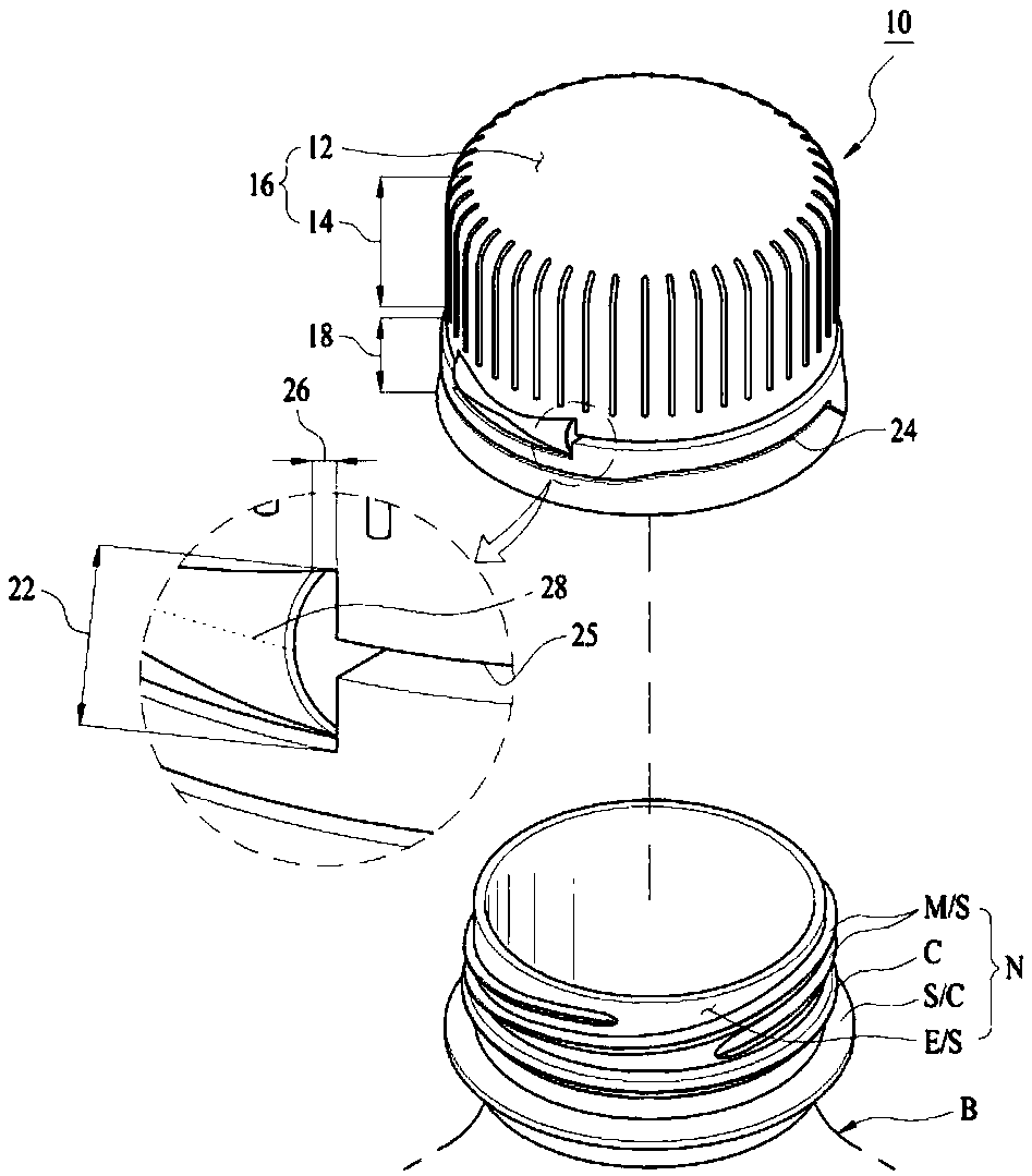
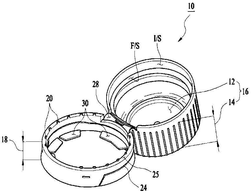
Owner:陈 宇翔

Mop hanger

InactiveCN106308712Aeasy to drainDoes not affect aesthetics
Owner:汪洋

Tire pressure display method and device for low-level configuration vehicles

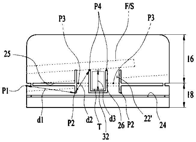
ActiveCN110194035Alow costDoes not affect aesthetics
Owner:深圳市雪锐科技有限公司

Adjustable-temperature cup

InactiveCN103654160AEasy to drinkDoes not affect aesthetics
Owner:WUXI DAAFU INFORMATION TECH

Classification and recommendation of technical efficacy words

  • Does not affect aesthetics

Adjustable-temperature cup

InactiveCN103654160AEasy to drinkDoes not affect aesthetics
Owner:WUXI DAAFU INFORMATION TECH

Tire pressure display method and device for low-level configuration vehicles

ActiveCN110194035Alow costDoes not affect aesthetics
Owner:深圳市雪锐科技有限公司

Civil aviation navigation device

InactiveCN109309322ADoes not affect aestheticsReduce chance of damage
Owner:陈 宇翔

Mop hanger

InactiveCN106308712Aeasy to drainDoes not affect aesthetics
Owner:汪洋
Why Eureka
Try Eureka