Shock absorber and washing machine comprising shock absorber
A technology of shock absorbers and chambers, which is applied to washing devices, other washing machines, textiles and papermaking, etc., and can solve problems such as invariable damping force and failure of shock absorbers
- Summary
- Abstract
- Description
- Claims
- Application Information
AI Technical Summary
Problems solved by technology
Method used
Image

Examples
Embodiment Construction
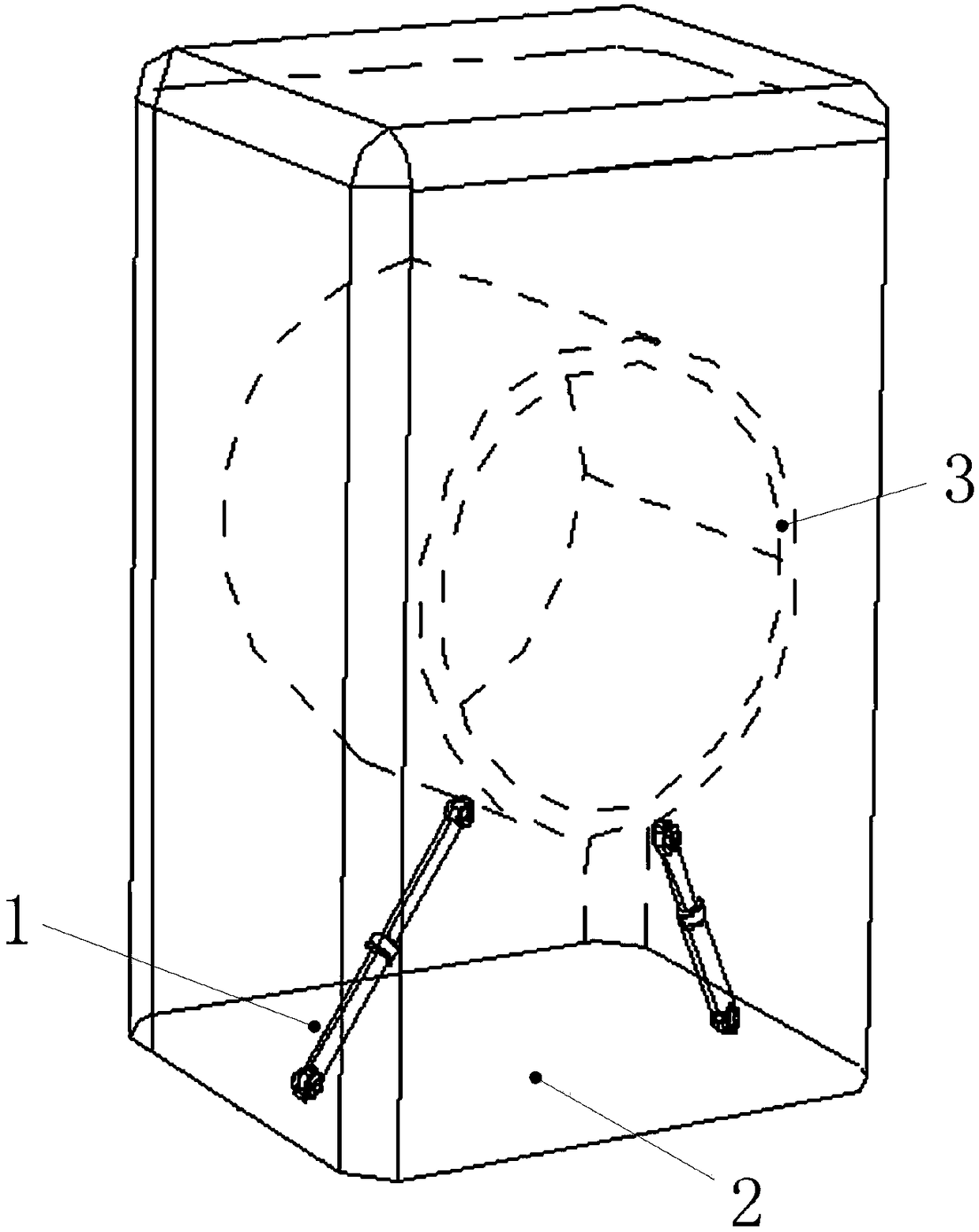
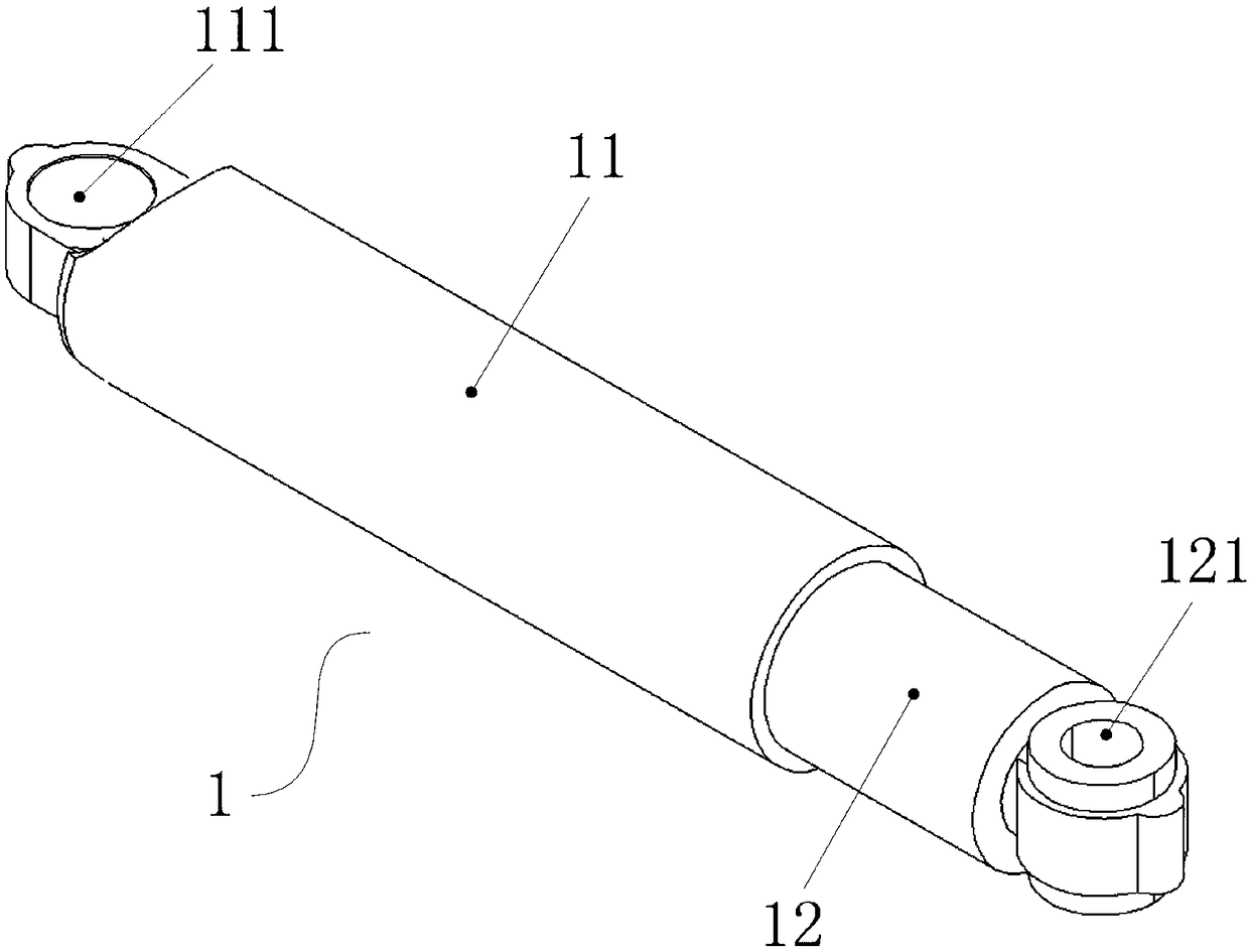
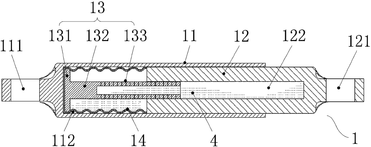
[0024] Preferred embodiments of the present invention are described below with reference to the accompanying drawings. Those skilled in the art should understand that these embodiments are only used to explain the technical principles of the present invention, and are not intended to limit the protection scope of the present invention. For example, although the description is described in conjunction with hydraulic oil, the present invention obviously can use other forms of fluid with a certain viscosity, as long as the fluid itself does not cause corrosion to the plunger and the liquid bladder.
[0025] It should be noted that, in the description of the present invention, the terms "center", "upper", "lower", "left", "right", "vertical", "horizontal", "inner", "outer" etc. The terms of the indicated direction or positional relationship are based on the direction or positional relationship shown in the drawings, which are only for the convenience of description, and do not ind...
PUM
| Property | Measurement | Unit |
|---|---|---|
| Angle | aaaaa | aaaaa |
Abstract
Description
Claims
Application Information
 - Generate Ideas
- Intellectual Property
- Life Sciences
- Materials
- Tech Scout
- Unparalleled Data Quality
- Higher Quality Content
- 60% Fewer Hallucinations
Browse by: Latest US Patents, China's latest patents, Technical Efficacy Thesaurus, Application Domain, Technology Topic, Popular Technical Reports.
© 2025 PatSnap. All rights reserved.Legal|Privacy policy|Modern Slavery Act Transparency Statement|Sitemap|About US| Contact US: help@patsnap.com