Shunt ring design method

A design method and shunt ring technology, which are applied in mechanical equipment, jet propulsion devices, gas turbine devices, etc., can solve the problems of reducing the ability and scope of stable operation, deterioration of the working state of the fan booster stage, and airflow impact, so as to shorten the calculation time. time, improve the air flow, and ensure the effect of stable work

Active Publication Date: 2019-02-26
AECC COMML AIRCRAFT ENGINE CO LTD
View PDF5 Cites 3 Cited by
  • Summary
  • Abstract
  • Description
  • Claims
  • Application Information

AI Technical Summary

Problems solved by technology

If the position of the splitter ring is not at an appropriate height, the airflow will hit the front edge of the splitter ring at a wrong angle, and the unhealthy flow field such as the vortex formed will directly cause the working state of the fan booster stage to deteriorate and reduce its stable working ability and range. This problem will become more prominent when the bypass ratio increases

Method used


Image

  • Shunt ring design method
  • Shunt ring design method
  • Shunt ring design method

Examples


Embodiment Construction

[0032] The technical solutions of the present invention will be described in further detail below with reference to the accompanying drawings and embodiments.

[0033] The specific embodiments of the present invention are for the convenience of further description of the concept of the present invention, the technical problems to be solved, the technical features constituting the technical solution and the technical effects brought about. It should be noted that the description of these embodiments does not constitute a limitation of the present invention. In addition, the technical features involved in the embodiments of the present invention described below may be combined with each other as long as they do not conflict with each other.

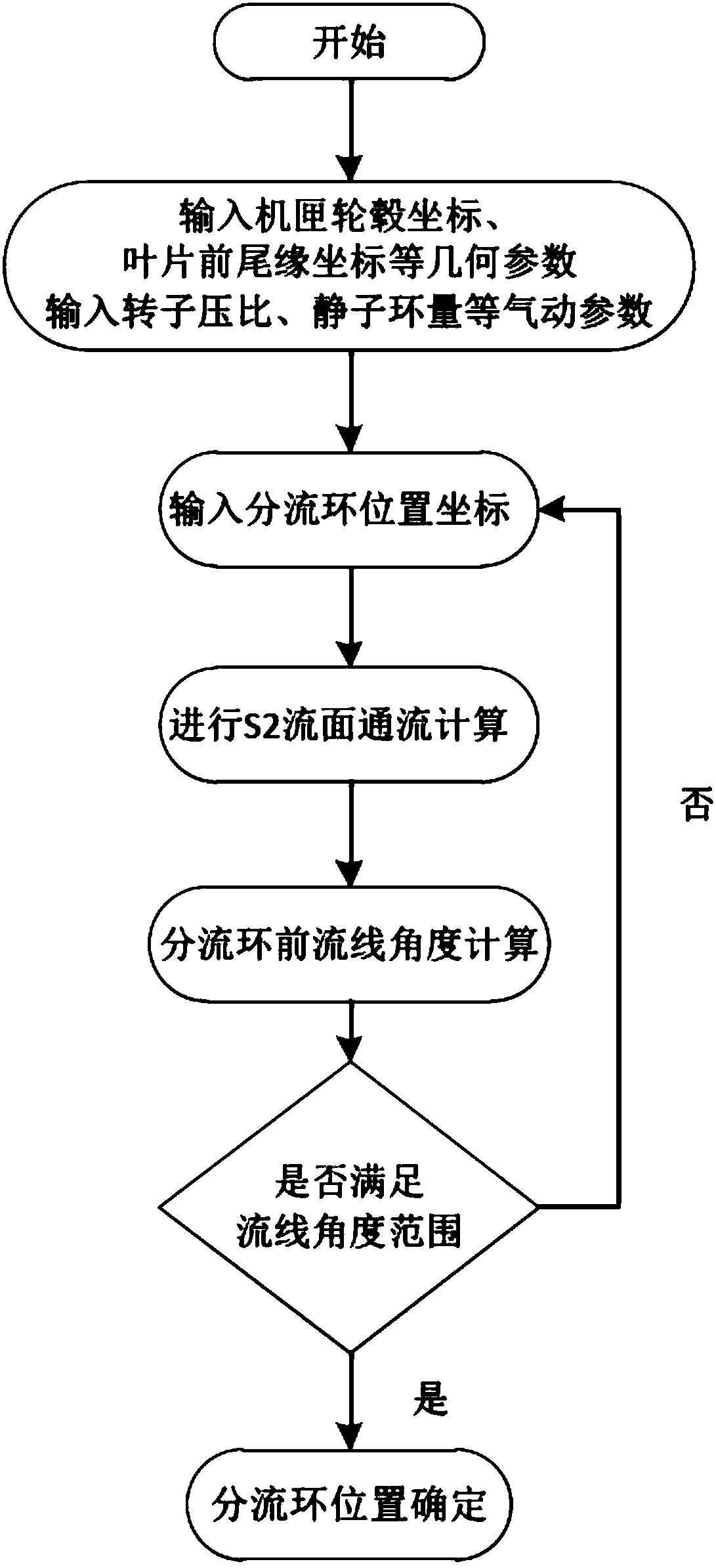
[0034] In order to simplify and solve the complex three-dimensional flow inside the turbomachinery, Mr. Wu Zhonghua proposed the quasi-three-dimensional idea of ​​the S1 and S2 flow surface iteration theory in 1952. Among them, the flow su...


PUM


Abstract

The invention relates to a shunt ring design method. The method includes a S2 streamline determining step: calculating the S2 stream surface flow passage according to a current position of a shunt ring to obtain a S2 streamline distribution result; a shunting ring leading edge streamline determining step: taking the leading edge streamline closest to the leading edge of the shunt ring in the S2 streamline as the shunt ring leading edge streamline; an included angle determining step: calculating an included angle alpha between a shunting ring center line of the shunt ring and the streamline ofthe leading edge of the shunt ring, if alpha is less than a preset angle value, determining the shunt ring position; and if the alpha is greater than or equal to the preset angle value, adjusting theposition of the shunt ring and returning to the S2 streamline determining step until the alpha is less than the preset angle value. The design method shortens the calculation time by determining and adjusting the angle range of the streamline angle of the leading edge of the shunt ring, realizes the design of a radial height position of the shunt ring under the specific bypass ratio, can improve the flow status of airflow near the shunt ring, and ensures the ability and range of stable operation of the fan booster stage.

Description

technical field [0001] The invention relates to the technical field of aero-engines, in particular to a design method for a splitter ring. Background technique [0002] The double-duct turbofan engine is an important form of aero-engine, which is developed from the turbojet engine. Compared with the turbojet engine, the main feature is that the area of ​​the first-stage compressor is much larger, and it is used as an air propeller ( Fan blades). The part through which the air of the core part passes becomes the inner duct, and the outer part of the core machine through which only the fan air passes becomes the outer duct. Among them, the part of the fan and the low-pressure compressor is also often called the fan booster stage. [0003] The splitter ring is a distribution structure that realizes the air entering the inner duct and the outer duct respectively, and is also an important part that affects the distribution of the air flow into the inner and outer ducts of the en...

Claims


Application Information

Patent Timeline
Patent Type & Authority Applications(China)
IPC IPC(8): F02C7/00
CPCF02C7/00
Inventor 刘晓锋裴小萌杨小贺
Owner AECC COMML AIRCRAFT ENGINE CO LTD
Why Eureka
Try Eureka