Humidifier water-draining control structure

A control structure and humidifier technology, applied in the air humidification system, heating and ventilation control system, heating mode, etc., can solve the problems of being opened, the humidifier cannot be taken out, etc., and achieve the effect of reducing production costs

Pending Publication Date: 2019-02-26
FOSHAN SHUNDE DEERMA ELECTRIC APPLIANCES CO LTD
View PDF8 Cites 2 Cited by
  • Summary
  • Abstract
  • Description
  • Claims
  • Application Information

AI Technical Summary

Problems solved by technology

[0003] However, there is a defect in the humidifier that uses a float to control the water level. The water tank of the humidifier cannot be taken out of the humidifier for water injection. The structure of the float + lever will drop down due to gravity after the water tank is taken out, so that the water connected by the lever The valve will be opened, so usually these humidifiers need to rely on the container to draw water and then fill the humidifier with water when filling

Method used


Image

  • Humidifier water-draining control structure
  • Humidifier water-draining control structure
  • Humidifier water-draining control structure

Examples


Embodiment Construction

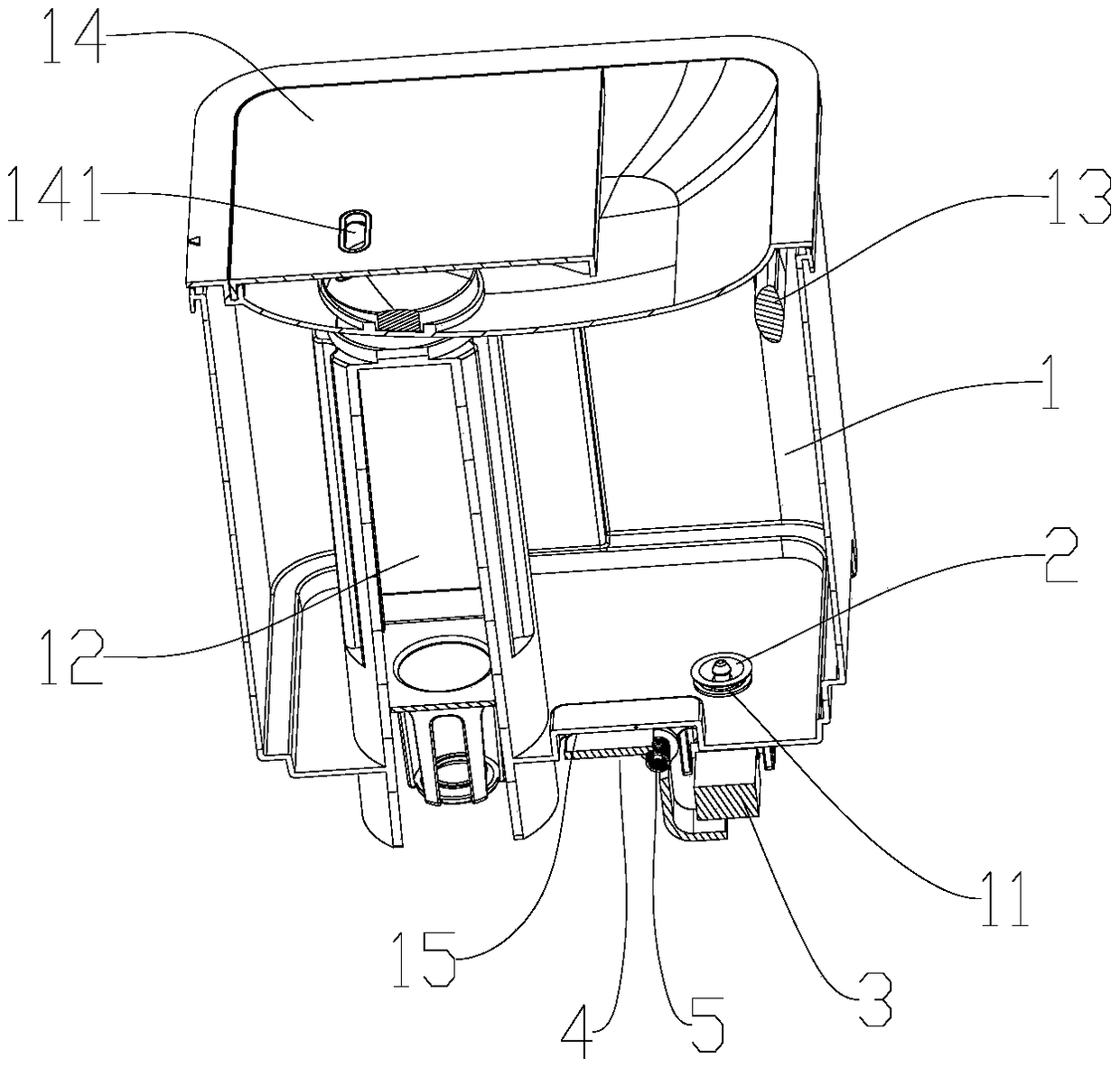
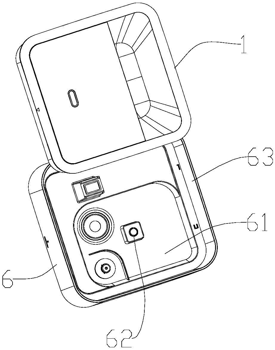
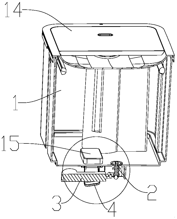
[0030] A water control structure of a humidifier according to the present invention will be described in conjunction with the accompanying drawings.

[0031] Such as Figures 1 to 12 The shown water control structure of a humidifier includes a body 6 of the humidifier and a detachable water tank 1 installed in the body 6. The body 6 provides support for the installation of the water tank 1, so that the water tank 1 can be stably placed on the body 6. To provide water support, an atomizer and an atomizing tank 61 matched therewith are provided on the body 6 correspondingly below the water tank 1, and a projection 62 extending upward in the atomizing tank 61, and a bottom of the water tank 1 is provided There are many functional components, and the atomizing tank 61 also provides space for these functional components at the bottom of the water tank 1, so that the functional components are accommodated in the atomizing tank 61, wherein these functional components include such as ...


PUM


Abstract

The invention discloses a humidifier water-draining control structure which comprises a humidifier body and a water tank detachably installed in the body. An atomizer and an atomizing groove matched with the atomizer are arranged at the lower portion, corresponding to the water tank, of the body, and the bottom of the water tank is provided with a water valve communicated with the atomizing groove. The humidifier water-draining control structure also comprises a floater, wherein the floater is hinged and installed at the bottom of the water tank and is connected with a water valve. The humidifier water-draining control structure also comprises a compressing plate and a torsional spring, wherein the torsional spring abuts against the compressing plate, so that the compressing plate lifts the floater to turn off the water valve. A convex block upwards extends in the atomizing groove and can be matched with the compressing plate, the convex block ejects the compressing plate open after the water tank is installed on the body, and the floater freely turns on and off the water valve. The water tank of a humidifier can be taken out and is kept sealed.

Description

technical field [0001] The invention relates to the field of humidifiers, in particular to a humidifier water control structure. Background technique [0002] The humidifier with water added from above, due to its special structure, the water tank is set above the atomization device of the humidifier, and the water can flow into the atomization device below naturally under the action of gravity, so there is no need to set up a pump like the traditional humidifier with water added from the bottom Pumping and humidifying, but it needs to control the amount of water flowing into the atomizing device below. Usually, a magnetic valve or a buoyancy valve is set to control the amount of water in the humidifier's water control structure. The magnetic valve needs to be controlled by an electrical signal, so it is necessary to set the water level. The sensor generates a water level signal, and then converts the water level signal into a control signal through the control panel to cont...

Claims


Application Information

Patent Timeline
Patent Type & Authority Applications(China)
IPC IPC(8): F24F6/12F24F11/49F24F11/89
CPCF24F6/12F24F11/49F24F11/89
Inventor 蔡演强曾勇胜
Owner FOSHAN SHUNDE DEERMA ELECTRIC APPLIANCES CO LTD
Why Eureka
Try Eureka