
Detonator lateral uniform illumination recognition structure

A technology for identifying structures and detonators, which is applied in the field of civil explosives, can solve problems such as inability to interconnect, errors, loss and circulation of civil explosives, etc., and achieve the effects of efficient information management, safety assurance, and strict management and control

Pending Publication Date: 2019-02-26
GUANGZHOU BENAN INFORMATION TECH CO LTD
View PDF0 Cites 0 Cited by
  • Summary
  • Abstract
  • Description
  • Claims
  • Application Information

AI Technical Summary

Problems solved by technology

[0003] At present, in the field of civil explosives, especially in the field of explosives and detonators that are frequently used, the management level is still lagging behind. At present, manual entry of the identification of civil explosives is basically used for management, resulting in low efficiency and frequent errors. It cannot be interconnected, nor can it be managed more effectively. This will lead to problems such as false claims, multiple claims, and inconsistent correspondence between people and objects, and the resulting loss of civil explosives is extremely serious. Seriously, with the rapid development of the Internet and transportation, the circulation of various information and materials is also accelerated and convenient. The cross-border circulation of civil explosives is also more convenient for the loss and circulation of civil explosives, and the resulting security risks It is also becoming more and more serious, so it is necessary to find a safe and reliable method to ensure the accurate relationship between people and explosives, so as to solve the increasingly serious problem of loss and circulation of explosives

Method used


Image

  • Detonator lateral uniform illumination recognition structure
  • Detonator lateral uniform illumination recognition structure
  • Detonator lateral uniform illumination recognition structure

Examples


Embodiment Construction

[0023] The embodiments described below by referring to the figures are exemplary only for explaining the present invention and should not be construed as limiting the present invention.

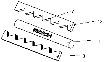
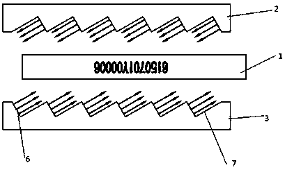
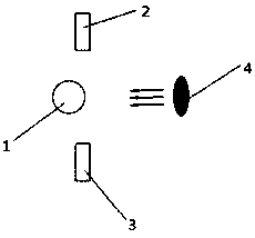
[0024] According to an embodiment of the present invention, such as Figure 1-4 As shown, the present invention proposes a structure for uniform illumination recognition of a detonator, including a direct illumination structure (2, 3 of which), the direct illumination structure includes an upper illuminating part 2 and a lower illuminating part 3, and the detonator with a logo 1 is installed between the upper illuminating part 2 and the lower illuminating part 3, and the upper illuminating part 2 and the lower illuminating part 3 have a light-emitting surface facing directly (such as image 3 shown) or the obliquely facing light-emitting surface that is deflected relative to the detonator axis (axis direction) and faces the direction of the detonator (such as Figure 4 shown).

[0025] Thro...


PUM


Abstract

The invention discloses a detonator lateral uniform illumination recognition structure, comprising a correlation illumination structure. The correlation illumination structure comprises an upper illumination component and a lower illumination component, a detonator with an identifier is installed between the upper illumination component and the lower illumination component, the upper illuminationcomponent and the lower illumination component have light-emitting surfaces for achieving positive correlation or light-emitting surfaces for achieving oblique correlation for deflecting relative to the axis of the detonator, and face the direction of the detonator. According to the invention, the identifier of the detonator can be illuminated, so generation of glare light can be avoided, thus avoiding the problem of an identification failure or unclear identification of the identifier.

Description

technical field [0001] The invention relates to the field of civil explosives, in particular to a detonator illumination identification structure. Background technique [0002] Explosives for civilian use (hereinafter referred to as explosives for civilian use) refer to various types of gunpowder, explosives and their products, detonators and other ignition and detonation materials that are used for non-military purposes and listed in the list of explosives for civilian use. Industrial energy and civil explosives play an important role in my country's economic construction and infrastructure construction. my country's economic construction and infrastructure construction are in the process of rapid development, so the amount of civil explosives required is extremely alarming. For The management of such items is increasingly valued and concerned by governments at all levels. [0003] At present, in the field of civil explosives, especially in the field of explosives and detona...

Claims


Application Information

Patent Timeline
Patent Type & Authority Applications(China)
IPC IPC(8): G03B15/03G06K9/32
CPCG03B15/03G06V20/62
Inventor 周安法王沛玉
Owner GUANGZHOU BENAN INFORMATION TECH CO LTD
Learn More