Cleaning device for paint bottles of handicrafts

A technology for cleaning devices and handicrafts, applied in the field of handicrafts, can solve the problems of incomplete cleaning and large floor space, and achieve the effect of improving the utilization rate of the room and reducing the floor space.

Pending Publication Date: 2019-03-01
HUZHOU SHANLIAN YONGHEFENG PEN HOUSE
View PDF0 Cites 3 Cited by
  • Summary
  • Abstract
  • Description
  • Claims
  • Application Information

AI Technical Summary

Problems solved by technology

[0004] The object of the present invention is to provide a cleaning device for handicraft paint bottles

Method used


Image

  • Cleaning device for paint bottles of handicrafts
  • Cleaning device for paint bottles of handicrafts
  • Cleaning device for paint bottles of handicrafts

Examples


Embodiment 1

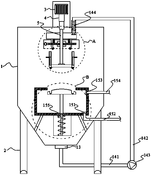
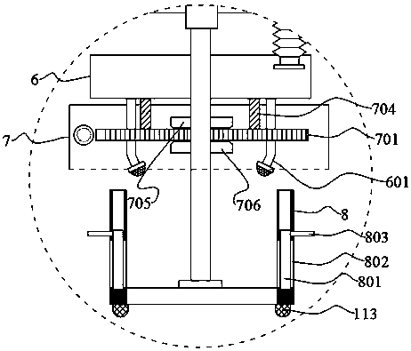
[0031] This embodiment includes a housing 1, the lower end of the housing 1 is provided with a water outlet 13, the lower end of the housing 1 is provided with a leg 2, and the upper end of the housing 1 is provided with a hydraulic cylinder 3, the hydraulic cylinder 3 The telescoping shaft 4 is connected with a connecting rod 5, and the lower end of the connecting rod 5 passes through the inner wall of the housing 1 and is connected with a cleaning box 8. The periphery of the connecting rod 5 is also provided with a water storage tank 6, and the water storage tank The lower end of 6 is connected with a plurality of nozzles 601; the bottom of the cleaning box 8 is also provided with a soaking box 9, and a support 10 is connected between the soaking box 9 and the housing 1, and the upper end of the soaking box 9 is provided with a cleaning box of the same size. 8 openings that match each other, the soaking box 9 is provided with a water baffle 11 that matches the size of the ope...

Embodiment 2

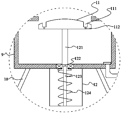
[0034]This embodiment is further optimized on the basis of Embodiment 1 as follows: the lifting device includes a hollow sleeve 121, a guide rod 123, a return spring 124, a limit block 122 and a storage box 12, and the hollow sleeve 121 The upper end is connected to the lower end of the water retaining plate 11. The lower end of the hollow sleeve 121 penetrates the outer wall of the soaking barrel and extends into the storage box 12. The storage box 12 is located at the lower end of the soaking box 9. The storage box 12 is provided with Guide rod 123, the lower end of the guide rod 123 is connected to the lower end inner wall of the storage box 12, the upper end of the guide rod 123 is inserted into the hollow sleeve 121 and connected to the stop block 122, and the return spring 124 sets Located outside the guide rod 123 , the return spring 124 is located between the hollow sleeve 121 and the inner wall of the lower end of the storage box 12 .

[0035] After adopting this tech...

Embodiment 3

[0037] This embodiment is further optimized on the basis of embodiment 2 as follows: a sealing ring 155 is arranged between the hollow sleeve 121 and the soaking tank 9 .

[0038] After adopting the outlined scheme, a sealing ring 155 is arranged between the hollow sleeve 121 and the outer wall of the soaking box 9, which effectively prevents the soaking liquid in the soaking box 9 from entering the storage box 12 when the hollow sleeve 121 moves up and down. Inside.


PUM


Abstract

The invention discloses a cleaning device for paint bottles of handicrafts. The problems of large floor space and incomplete cleaning of an existing cleaning device are solved. The cleaning device forthe paint bottles of the handicrafts comprises a shell. A water outlet is formed in the lower end of the shell, and supporting legs are arranged at the lower end of the shell. A hydraulic cylinder isarranged at the upper end of the shell, and a telescopic shaft of the hydraulic cylinder is connected with a connecting rod. The lower end of the connecting rod is connected with a cleaning box afterpenetrating through the inner wall of the shell, a water storage tank further sleeves the periphery of the connecting rod, and a plurality of sprinklers are connected to the lower end of the water storage tank. A soaking tank is further arranged on the lower part of the cleaning tank, and a bracket is connected between the soaking tank and the shell. An opening of which the size is matched with the size of the cleaning tank is formed in the upper end of the soaking tank, the soaking tank is internally provided with a water stopping plate matched with the size of the opening, and the water stopping plate is connected with a lifting device. A liquid inlet is formed in the side wall of the soaking tank, and a liquid outlet is formed in the lower end of the soaking tank.

Description

technical field [0001] The invention relates to the technical field of handicrafts, in particular to a cleaning device for paint bottles of handicrafts. Background technique [0002] In the process of making handicrafts, a large amount of paint is needed, and after the paint bottle is filled for a period of time, a large amount of paint will adhere to the inner wall of the paint bottle, so when configuring new paint again, the paint bottle needs to be cleaned to ensure that the paint quality [0003] However, in the prior art, most of the cleaning of paint bottles is done manually. However, this method not only has low efficiency, but also has some damage to the human body. Therefore, some cleaning devices have been realized on the market. However, the existing cleaning Due to the unreasonable design of the device, it occupies a large area; and it can only be cleaned in one direction, resulting in incomplete cleaning. Contents of the invention [0004] The object of the ...

Claims


Application Information

Patent Timeline
IPC IPC(8): B08B9/28B08B13/00
CPCB08B9/28B08B13/00
Inventor 王小卫
Owner HUZHOU SHANLIAN YONGHEFENG PEN HOUSE
Why Eureka
Try Eureka