Magnet assembly jig

A technology of magnets and jigs, which is applied in the direction of manufacturing tools, workpiece clamping devices, metal processing, etc., can solve the problems of jig tilt, inconvenient production, time-consuming and labor-intensive problems, and achieve the effect of ensuring stamping quality and improving production efficiency

Pending Publication Date: 2019-03-01
SUZHOU BENTENG PLASTIC
View PDF0 Cites 3 Cited by
  • Summary
  • Abstract
  • Description
  • Claims
  • Application Information

AI Technical Summary

Problems solved by technology

In the prior art, the magnet assembly jig is a jig for assembling magnets for workpieces. Before the assembly starts, the lower plate of the jig needs to be fixed. The original jig usually fixes the four corners of the lower plate with bolts. It is more troublesome, and if the bolts are not on the same level, the jig will be tilted, which will affect its processing quality; more importantly, during assembly, the magnet needs to be transported to the designated position for press-fitting, and ordinary assembly jigs are inconvenient. The magnet is automatically transported to the designated position, which brings inconvenience to the production; at the same time, the current manual fixture can only be operated individually, which is time-consuming and laborious

Method used


Image

  • Magnet assembly jig
  • Magnet assembly jig
  • Magnet assembly jig

Examples


Embodiment Construction

[0024] The following will clearly and completely describe the technical solutions in the embodiments of the present invention with reference to the accompanying drawings in the embodiments of the present invention. Obviously, the described embodiments are only some, not all, embodiments of the present invention. Based on the embodiments of the present invention, all other embodiments obtained by persons of ordinary skill in the art without making creative efforts belong to the protection scope of the present invention.

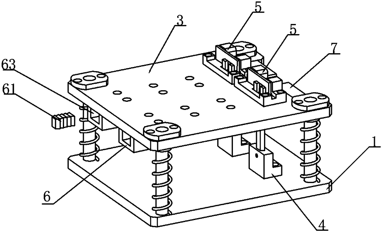
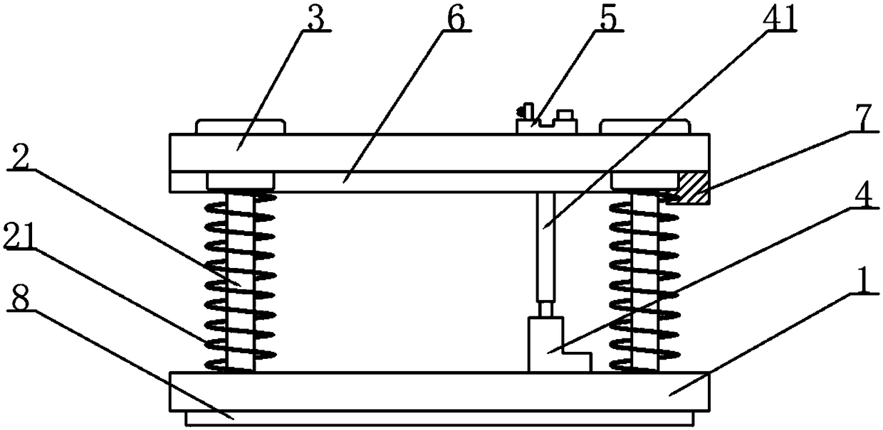
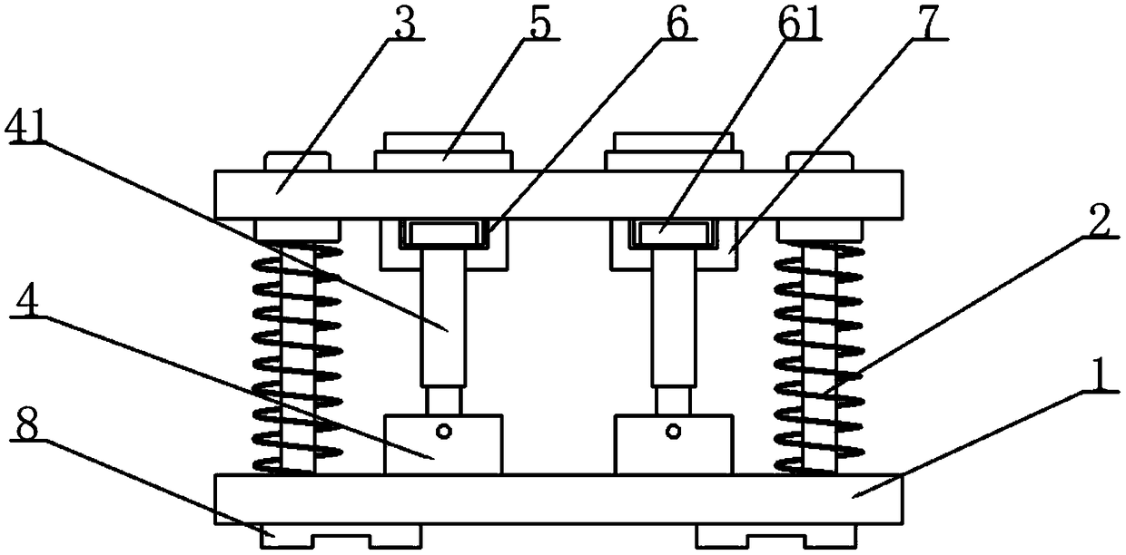
[0025] see Figure 1-5 , the present invention discloses a magnet assembly jig, comprising a relatively movable upper plate 3 and a lower plate 1, the top of the lower plate 1 is fixedly connected with a guide post 2, and the outer wall of the guide post 2 is fixedly connected There is a spring 21, the top of the guide post 2 is slidably connected to the upper plate 3, and the two ends of the spring 21 respectively abut against the upper surface of the lower p...


PUM


Abstract

The invention discloses a magnet assembly jig. The magnet assembly jig comprises an upper plate and a lower plate, wherein the upper plate and the lower plate are arranged in a manner of being capableof relatively moving. Ejector rods are arranged on the lower plate. Product locating parts used for containing products are fixedly arranged on the upper surface of the upper plate. A through hole isformed in the upper surface of each product locating part. The bottom of the upper plate is fixedly connected with channels. The inner side wall of each channel is in sliding connection with a magnet. An ejector rod groove is formed in the outer side wall of each channel. Openings used for allowing the magnets to enter therein are formed in the first ends of the channels, and force application parts used for driving the magnets to move are arranged at the second ends of the channels. According to the magnet assembly jig, the upper plate is driven by a punching machine to be pressed down, andtherefore the ejector rods press the magnets in the channels into the products; and an iron block is arranged on one side of each channel, only the iron blocks in the whole jig are made of irony materials, the magnets can move only through attraction of the iron blocks, the iron blocks attract the magnets in the channels into the ejector rod grooves, automatic conveying is completed, and thereforethe production efficiency is improved.

Description

technical field [0001] The invention belongs to the technical field of assembly jigs, and in particular relates to a magnet assembly jig. Background technique [0002] Fixture is a large category of tools for woodworking, ironwork, fitter, machinery, electric control and other handicrafts. It is mainly used as a tool to assist in controlling position or movement (or both). Fixtures can be divided into assembly categories Fixtures, test fixtures, etc. Assembly fixtures include assembly fixtures, welding fixtures, disassembly fixtures, glue dispensing fixtures, irradiation fixtures, adjustment fixtures and cutting fixtures. Assembly fixtures are Fixtures for workpiece assembly parts. In the prior art, the magnet assembly jig is a jig for assembling magnets for workpieces. Before the assembly starts, the lower plate of the jig needs to be fixed. The original jig usually fixes the four corners of the lower plate with bolts. It is more troublesome, and if the bolts are not on t...

Claims


Application Information

Patent Timeline
Patent Type & Authority Applications(China)
IPC IPC(8): B23P19/02B25B11/02
CPCB23P19/02B25B11/02
Inventor 董雪锋刘新院宋明明
Owner SUZHOU BENTENG PLASTIC
Why Eureka
Try Eureka