
Stainless steel plate assembly mechanism

A stainless steel plate and assembly mechanism technology, which is applied in metal processing, metal processing equipment, manufacturing tools, etc., can solve the problems of scratches on the side wall of the plug-in rod, affect the installation quality, and troublesome installation, so as to improve the installation quality and effect Good, easy to install

Inactive Publication Date: 2019-03-01
戴燕青
View PDF0 Cites 5 Cited by
  • Summary
  • Abstract
  • Description
  • Claims
  • Application Information

AI Technical Summary

Problems solved by technology

[0002] When the existing stainless steel plate and the insertion rod are plugged and fixed, generally after the stainless steel plate is fixed, the insertion rod is manually placed on the top surface of the stainless steel plate, and then it is knocked into the stainless steel plate by beating. It is troublesome to install, and it is easy to be deformed by manual knocking;
[0003] In some automatic pressing mechanisms, the insertion rod needs to be clamped by a clamping block and then pressed into the stainless steel plate. When clamping, it is easy to cause scratches on the side wall of the insertion rod, which affects the installation quality.

Method used


Image

  • Stainless steel plate assembly mechanism

Examples


Embodiment Construction

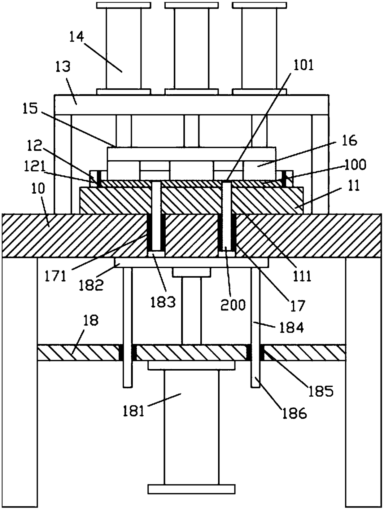
[0014] Examples, see e.g. figure 1 As shown, a stainless steel plate assembly mechanism includes a frame 10, a fixed block 11 is fixed in the middle of the top plate of the top plate of the frame 10, and a limit frame 12 is fixed on the top edge of the fixed block 11. The frame 10 The top surface of the top plate is fixed with an upper support frame 13, and the top surface of the top plate of the upper support frame 13 is fixed with a plurality of compression oil cylinders 14, and the push rods of all compression oil cylinders 14 pass through the bottom surface of the top plate of the upper support frame 13 and are fixed. There is a compression plate 15, the bottom surface of the compression plate 15 is fixed with a plurality of compression blocks 16, the stainless steel plate 100 to be assembled is inserted and sleeved in the limit frame 12 and pressed against the top surface of the fixed block 11, the compression blocks 16 is pressed against the top surface of the stainless ...


PUM


Abstract

The invention discloses a stainless steel plate assembly mechanism. The stainless steel plate assembly mechanism comprises a rack, wherein the middle part of the top surface of the top plate of the rack is fixedly equipped with a fixed block; the side part of the top surface of the fixed block is fixedly equipped with a limiting frame body; the top surface of the top plate of the rack is fixedly equipped with an upper supporting frame; the top surface of the top plate of the upper supporting frame is fixedly equipped with a plurality of pressing oil cylinders; pushing rods of all pressing oilcylinders penetrate through the bottom surface of the top plate of the upper supporting frame, and are fixedly equipped with a pressing plate; the bottom surface of the pressing plate is fixedly equipped with a plurality of pressing blocks; a to-be-assembled stainless steel plate is in plug bush in the limiting frame body and presses against the top surface of a fixed block; the pressing blocks press against the top surface of the to-be-assembled stainless steel plate; a plurality of blocking through holes are formed in the to-be-assembled stainless steel plate; and the blocking through holesare aligned to the corresponding jacks in the bottom surface of the fixed block up and down. The stainless steel plate assembly mechanism can automatically mount a to-be-spliced rod onto the to-be-assembled stainless steel plate, is convenient in mounting, is good in effect, does not need to clamp the to-be-spliced rod, guarantees the smooth outer surface of the to-be-spliced rod, does not generate scratches, and improves mounting quality.

Description

Technical field: [0001] The invention relates to the technical field of stainless steel processing equipment, in particular to a stainless steel plate assembly mechanism. Background technique: [0002] When the existing stainless steel plate and the insertion rod are plugged and fixed, generally after the stainless steel plate is fixed, the insertion rod is manually placed on the top surface of the stainless steel plate, and then it is knocked into the stainless steel plate by beating. It is troublesome to install, and it is easy to be deformed by manual knocking; [0003] And in some automatic pressing mechanisms, its insertion rod needs to be clamped with the clamping block and then pressed into the stainless steel plate, which easily makes the side wall of the insertion rod produce scratches etc. during its clamping, which affects the installation quality. Invention content: [0004] The purpose of the present invention is to overcome the deficiencies of the prior art ...

Claims


Application Information

Patent Timeline
Patent Type & Authority Applications(China)
IPC IPC(8): B23P19/027
CPCB23P19/027
Inventor 戴燕青
Owner 戴燕青
Features
  • Generate Ideas
  • Intellectual Property
  • Life Sciences
  • Materials
  • Tech Scout
  • Unparalleled Data Quality
  • Higher Quality Content
  • 60% Fewer Hallucinations
Learn More