Supercharge Your Innovation With Domain-Expert AI Agents!

Four-position stroke controller for part-turn valve electric device

A stroke controller and valve electric technology, which is applied in the direction of valve device, valve operation/release device, valve details, etc., can solve the problems that the stroke setting value cannot be adjusted continuously, the manufacturing process is difficult, the structure is complicated, etc., and it can be checked and adjusted. The valve is intuitive, easy to operate, and the effect of improving work efficiency

Active Publication Date: 2019-03-01
常州电站辅机股份有限公司
View PDF6 Cites 0 Cited by
  • Summary
  • Abstract
  • Description
  • Claims
  • Application Information

AI Technical Summary

Problems solved by technology

[0002] For the cam stroke control mechanism with holes, the stroke setting value cannot be adjusted continuously, but can only be adjusted step by step; or the screw transmission linear stroke control mechanism, the contact between its nut (contact block) and the micro switch is asymptotic. It is also in the form of gradual departure, so the action insensitive area of ​​the micro switch becomes a part of the insensitive area of ​​the stroke control mechanism
In addition, when the stroke of the electric device exceeds the control point of the travel switch, the micro switch will be crushed.
[0003] The counting and carrying gear transmission stroke control mechanism has high control precision and convenient adjustment, but the structure is complex and the manufacturing process is difficult, and it is generally used in multi-turn valves.

Method used


Image

  • Four-position stroke controller for part-turn valve electric device
  • Four-position stroke controller for part-turn valve electric device
  • Four-position stroke controller for part-turn valve electric device

Examples


Embodiment Construction

[0057] The present invention is described in further detail now in conjunction with accompanying drawing. These drawings are all simplified schematic diagrams, which only illustrate the basic structure of the present invention in a schematic manner, so they only show the configurations related to the present invention.

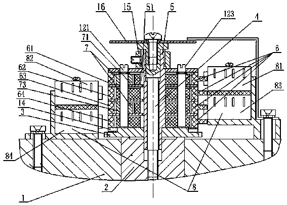
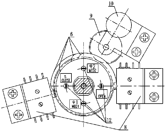
[0058] Such as Figure 1-4 The four-position stroke controller for the part-turn valve electric device shown includes box body 1, output shaft 2, degree opening gear 3, set screw 4, positioning sleeve 5, cam group 6, pinion group 7, micro-motion Switch group 8, transition gear 9, potentiometer 10, spacer group 11 and small shaft group 12;

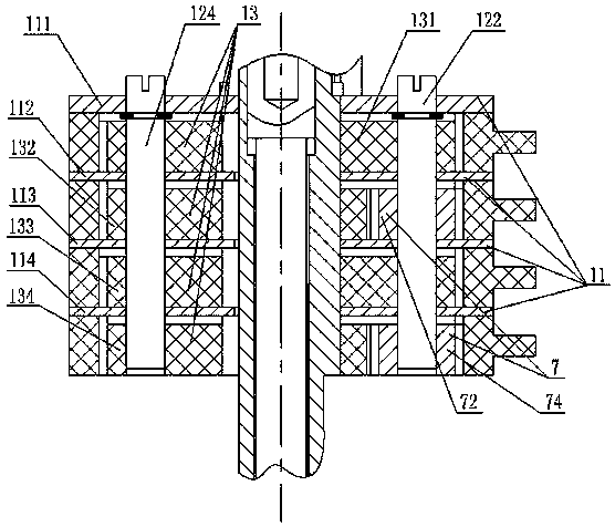
[0059] The cam group 6 has a first cam 61 at the top, a second cam 62 at the second layer, a third cam 63 at the third layer and a fourth cam 64 at the bottom;

[0060] The pinion set 7 has a first pinion 71 , a second pinion 72 , a third pinion 73 and a fourth pinion 74 ;

[0061] The microswitch group 8 is fixedly inst...


PUM


Abstract

The invention discloses a four-position stroke controller for a part-turn valve electric device. The four-position stroke controller comprises a box body, an output shaft, an open main gear, a stopperscrew, a positioning sleeve, a cam unit, a pinion unit, a micro-switch unit, a transition gear, a potentiometer, a spacer unit and a small shaft unit, wherein the micro-switch unit is fixed to the box body; the cam unit comprises a first cam, a second cam, a third cam and a fourth cam which are sequentially arranged from top to bottom; the pinion unit comprises a first pinion, a second pinion, athird pinion and a fourth pinion; the micro-switch unit comprises a first micro-switch, a second micro-switch, a third micro-switch and a fourth micro-switch; the first micro-switch and the third micro-switch form the first group of micro-switches, are positioned at one side of the cam unit and are arranged from top to bottom; and the second micro-switch and the fourth micro-switch form the second group of micro-switches, are positioned at the other side of the cam unit and are arranged from top to bottom. The four-position stroke controller disclosed by the invention is simple and convenientto operate and can be used for checking and regulating a valve more intuitively and conveniently; the stroke setting value of the four-position stroke controller can be continuously regulated; the work stability of equipment is improved; and thus the work efficiency is improved.

Description

technical field [0001] The invention relates to the technical field of electric devices for partial rotary valves, in particular to a four-position stroke controller for electric devices for partial rotary valves. Background technique [0002] For the cam stroke control mechanism with holes, the stroke setting value cannot be adjusted continuously, but can only be adjusted step by step; or the screw transmission linear stroke control mechanism, the contact between its nut (contact block) and the micro switch is asymptotic. It is also in the form of gradual departure, so the action insensitive area of ​​the micro switch becomes a part of the insensitive area of ​​the travel control mechanism. In addition, when the stroke of the electric device exceeds the control point of the travel switch, the micro switch will be crushed. [0003] The counting gear transmission type stroke control mechanism has high control precision and convenient adjustment, but the structure is complex ...

Claims


Application Information

Patent Timeline
Patent Type & Authority Applications(China)
IPC IPC(8): F16K31/02F16K31/52F16K31/53F16K37/00
CPCF16K31/02F16K31/52F16K31/53F16K37/0008
Inventor 徐洁杨俊糜建立刘亚男
Owner 常州电站辅机股份有限公司
Features
  • R&D
  • Intellectual Property
  • Life Sciences
  • Materials
  • Tech Scout
  • Unparalleled Data Quality
  • Higher Quality Content
  • 60% Fewer Hallucinations
Learn More