Optical imaging system

An optical imaging system and imaging surface technology, applied in optics, optical components, instruments, etc., can solve the problems of high pixel and low cost, and achieve the effect of high resolution and low cost

Pending Publication Date: 2019-03-01
ZHEJIANG SUNNY OPTICAL CO LTD
View PDF0 Cites 14 Cited by
  • Summary
  • Abstract
  • Description
  • Claims
  • Application Information

AI Technical Summary

Problems solved by technology

[0002] In recent years, with the continuous upgrading of electronic products such as smartphones and tablets

Method used


Image

  • Optical imaging system
  • Optical imaging system
  • Optical imaging system

Examples


Example Embodiment

[0065] Example 1

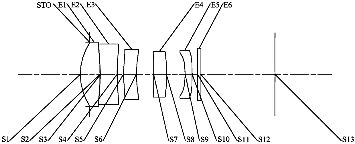
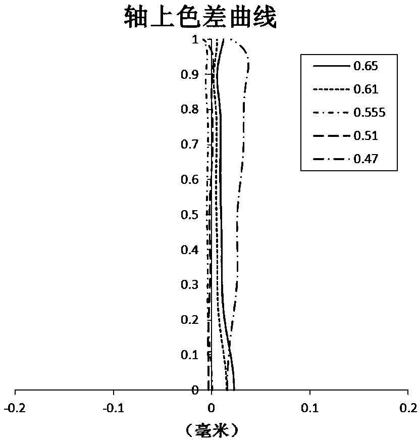
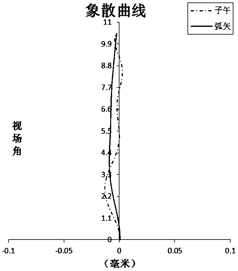
[0066] The following reference Figure 1 to Figure 2D The optical imaging system according to Embodiment 1 of the present application is described. figure 1 A schematic structural diagram of an optical imaging system according to Embodiment 1 of the present application is shown.

[0067] Such as figure 1 As shown, the optical imaging system according to the exemplary embodiment of the present application includes in order from the object side to the image side along the optical axis: a stop STO, a first lens E1, a second lens E2, a third lens E3, and a fourth lens E4 , The fifth lens E5, the filter E6 and the imaging surface S13.

[0068] The first lens E1 has a positive refractive power, the object side surface S1 is convex, and the image side surface S2 is convex. The second lens E2 has negative refractive power, the object side surface S3 is a concave surface, and the image side surface S4 is a concave surface. The third lens E3 has negative refractive power,...

Example Embodiment

[0094] Example 2

[0095] The following reference Figure 3 to Figure 4D The optical imaging system according to Embodiment 2 of the present application is described. In this embodiment and the following embodiments, for the sake of brevity, some descriptions similar to Embodiment 1 will be omitted. image 3 A schematic structural diagram of an optical imaging system according to Embodiment 2 of the present application is shown.

[0096] Such as image 3 As shown, the optical imaging system according to the exemplary embodiment of the present application includes in order from the object side to the image side along the optical axis: a stop STO, a first lens E1, a second lens E2, a third lens E3, and a fourth lens E4 , The fifth lens E5, the filter E6 and the imaging surface S13.

[0097] The first lens E1 has a positive refractive power, the object side surface S1 is convex, and the image side surface S2 is convex. The second lens E2 has negative refractive power, the object side...

Example Embodiment

[0109] Example 3

[0110] The following reference Figure 5 to Figure 6D The optical imaging system according to Embodiment 3 of the present application is described. Figure 5 A schematic structural diagram of an optical imaging system according to Embodiment 3 of the present application is shown.

[0111] Such as Figure 5 As shown, the optical imaging system according to the exemplary embodiment of the present application includes in order from the object side to the image side along the optical axis: a stop STO, a first lens E1, a second lens E2, a third lens E3, and a fourth lens E4 , The fifth lens E5, the filter E6 and the imaging surface S13.

[0112] The first lens E1 has a positive refractive power, the object side surface S1 is convex, and the image side surface S2 is convex. The second lens E2 has negative refractive power, the object side surface S3 is a concave surface, and the image side surface S4 is a concave surface. The third lens E3 has negative refractive powe...


PUM


Abstract

The invention discloses an optical imaging system. The system successively comprises a first lens, a second lens, a third lens, a fourth lens and a fifth lens from an object side to an image side along an optical axis. The first lens has positive focal power, and an object side surface is a convex surface; the second lens has negative focal power; the third lens has the negative focal power, and the image side surface is a concave surface; the fourth lens has the positive focal power or the negative focal power; and the fifth lens has the negative focal power, and the object side surface is the concave surface. The distance TTL from the object side surface of the first lens to the imaging surface of the optical imaging system on the optical axis, the total effective focal length f of the optical imaging system, and the half ImgH of the diagonal length of an effective pixel area on the imaging surface of the optical imaging system satisfy the following conditional expressions: TTL/f<=0.95 and f/ImgH>4.5.

Description

Technical field [0001] The present application relates to an optical imaging system, and more specifically, to an optical imaging system including five lenses. Background technique [0002] In recent years, with the continuous updating of electronic products such as smart phones and tablets, optical imaging systems applied to them are facing the challenges of high pixels, low cost, and ultra-thinness. However, for most mid-to-low-end models, the five-piece lens system is still an important choice for cost control considerations. [0003] The major smart terminal manufacturers are increasingly pursuing the high resolution and thinness of the lens, and the large working image area and short system length have become the main factors concerned by the major smart terminal manufacturers. Large working image area means that it is possible to provide higher image resolution, and the short overall system length means that the lens can be thinner and lighter. The realization of large work...

Claims


Application Information

Patent Timeline
IPC IPC(8): G02B13/00G02B13/18
CPCG02B13/0045G02B13/18
Inventor 黄林戴付建赵烈烽
Owner ZHEJIANG SUNNY OPTICAL CO LTD
Why Eureka
Try Eureka