Supercharge Your Innovation With Domain-Expert AI Agents!

Scanning galvanometer

A scanning galvanometer and scanning mirror technology, applied in the field of scanning galvanometers, can solve the problems of unable to control scanning frequency and scanning angle, unable to achieve precise control of field of view scanning, etc., to achieve the effect of precise control

Pending Publication Date: 2019-03-01
SUTENG INNOVATION TECH CO LTD
View PDF0 Cites 0 Cited by
  • Summary
  • Abstract
  • Description
  • Claims
  • Application Information

AI Technical Summary

Problems solved by technology

[0004] However, in the resonant scanning mirror, one axis is forced to vibrate, so the scanning frequency and scanning angle of this axis cannot be controlled, and thus the precise control of field of view scanning cannot be realized

Method used


Image

  • Scanning galvanometer
  • Scanning galvanometer
  • Scanning galvanometer

Examples


Embodiment Construction

[0029] In order to make the purpose, technical solution and advantages of the present application clearer, the present application will be further described in detail below in conjunction with the accompanying drawings and embodiments. It should be understood that the specific embodiments described here are only used to explain the present application, and are not intended to limit the present application.

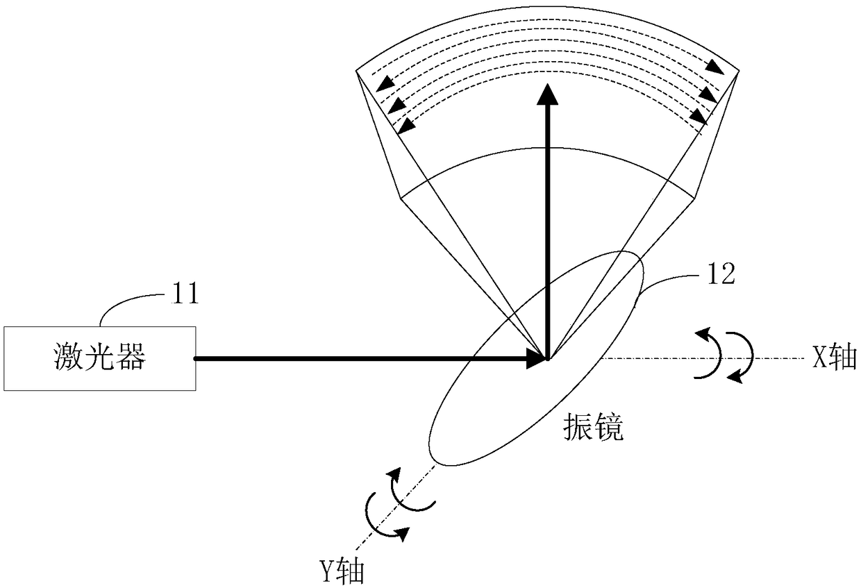
[0030] The scanning vibrating mirror provided by the application is used as a MEMS (Micro-Electro-Mechanical System, Micro-Electro-MechanicalSystem) device, and can be applied to such as figure 1 shown in the application environment. Wherein, the laser 11 can emit a pulsed laser signal and project it on the vibrating mirror 12, which is reflected by the vibrating mirror 12, and the laser echo signal reflected by the object is received by a laser receiver (not shown); The laser signal sending time and the laser echo signal receiving time are used to obtain the flight time ...


PUM


Abstract

The present invention relates to a scanning galvanometer, and the scanning galvanometer comprises: an anchoring structure, a differential capacitance driver, a connecting rod transmission module and ascanning mirror module. The differential capacitance driver is fixed on the anchoring structure, and comprises an X-axis driver, a Y-axis driver, and a driving circuit. The connecting rod driving module comprises an X-axis connecting rod mechanism and a Y-axis connecting rod mechanism. The X-axis driver is configured to drive the X-axis connecting rod mechanism to swing under an electrostatic force generated by a first driving voltage outputted by the driving circuit, thereby driving the scanning mirror module to swing around the Y axis. The Y-axis driver is configured to drive the Y-axis connecting rod mechanism to swing under an electrostatic force generated by a second driving voltage outputted by the driving circuit, thereby driving the scanning mirror module to swing around the X-axis. The swinging angle of the scanning mirror module around the Y axis is corresponding to the frequency and the first driving voltage, and the swinging angle around the X axis is corresponding to thefrequency and the second driving voltage. The scanning galvanometer can independently and precisely control the scanning frequencies and scanning angles of the scanning mirror module around the X-axisand the Y-axis.

Description

technical field [0001] The present application relates to the technical field of laser radar, in particular to a scanning vibrating mirror. Background technique [0002] As a commonly used ranging sensor, lidar has an important application in unmanned driving systems due to its high resolution and low interference from environmental factors. It is generally used for field of view scanning. However, unmanned driving systems require lidar to have high imaging frame rate, high resolution, long-range ranging capability, small size, and high reliability, and traditional lidar systems are difficult to meet such performance requirements. [0003] Resonant scanning mirror, as a relatively mature field of view scanning method at present, drives the scanning mirror to perform high-frequency resonance around one of the horizontal or vertical axes through the electromagnetic field generated by the current in the microcoil, and at the same time the scanning mirror rotates around the othe...

Claims


Application Information

Patent Timeline
Patent Type & Authority Applications(China)
IPC IPC(8): G02B26/10
CPCG02B26/101G02B26/105
Inventor 邱纯鑫刘乐天
Owner SUTENG INNOVATION TECH CO LTD
Features
  • R&D
  • Intellectual Property
  • Life Sciences
  • Materials
  • Tech Scout
  • Unparalleled Data Quality
  • Higher Quality Content
  • 60% Fewer Hallucinations
Learn More