Permanent magnet undulator with adjustable polarization

A permanent magnet wave and polarization technology, applied in the field of synchrotron radiation, it can solve the problems of the same peak magnetic field strength of Knot, the same main magnetic field, low Knot structure efficiency, low radiation flux, etc., and achieve the effect of improving inherent defects.

Inactive Publication Date: 2019-03-01
INST OF HIGH ENERGY PHYSICS CHINESE ACAD OF SCI
View PDF4 Cites 5 Cited by
  • Summary
  • Abstract
  • Description
  • Claims
  • Application Information

AI Technical Summary

Problems solved by technology

Due to the limitation outside the vacuum, the magnetic field strength of the APPLE-Knot type undulator cannot be compared with that of the Delta type vacuum inner structure, and the lower magnetic field strength also leads to lower radiation flux
At the same time, the inherent two-fold symmetry of the APPLE-II magnetic structure also makes the maximum magnetic field strength in one orthogonal direction smaller than that in the other orthogonal direction, which makes it impossible for users to obtain optimal radiation performance in all polarization modes.
After introducing the knot structure, its knot magnetic field also continues this shortcoming. At the same time, the knot magnetic array farther away from the beam center further enlarges the gap between the knot magnetic field strength and the main magnetic field strength, resulting in the radiation power deflection efficiency in the linear polarization mode. In order to solve the shortcomings of the low efficiency of the Knot structure, Professor Qiao Shan of Shanghai University proposed the APPLE-Knot structure of the four-row magnetic array
However, this structure still cannot solve the defects caused by the inherent bifold symmetry outside the vacuum of the APPLE-II structure, and its knot peak magnetic field strength is still not the same as the main magnetic field. Therefore, it is necessary to make a certain compromise on the strength of the knot magnetic field, so that the power deflection efficiency of the knot structure is slightly reduced.

Method used


Image

  • Permanent magnet undulator with adjustable polarization
  • Permanent magnet undulator with adjustable polarization
  • Permanent magnet undulator with adjustable polarization

Examples


Embodiment Construction

[0063] Preferred embodiments of the present invention will be described in detail below in conjunction with the accompanying drawings, wherein the accompanying drawings constitute a part of the application and together with the embodiments of the present invention are used to explain the principle of the present invention and are not intended to limit the scope of the present invention.

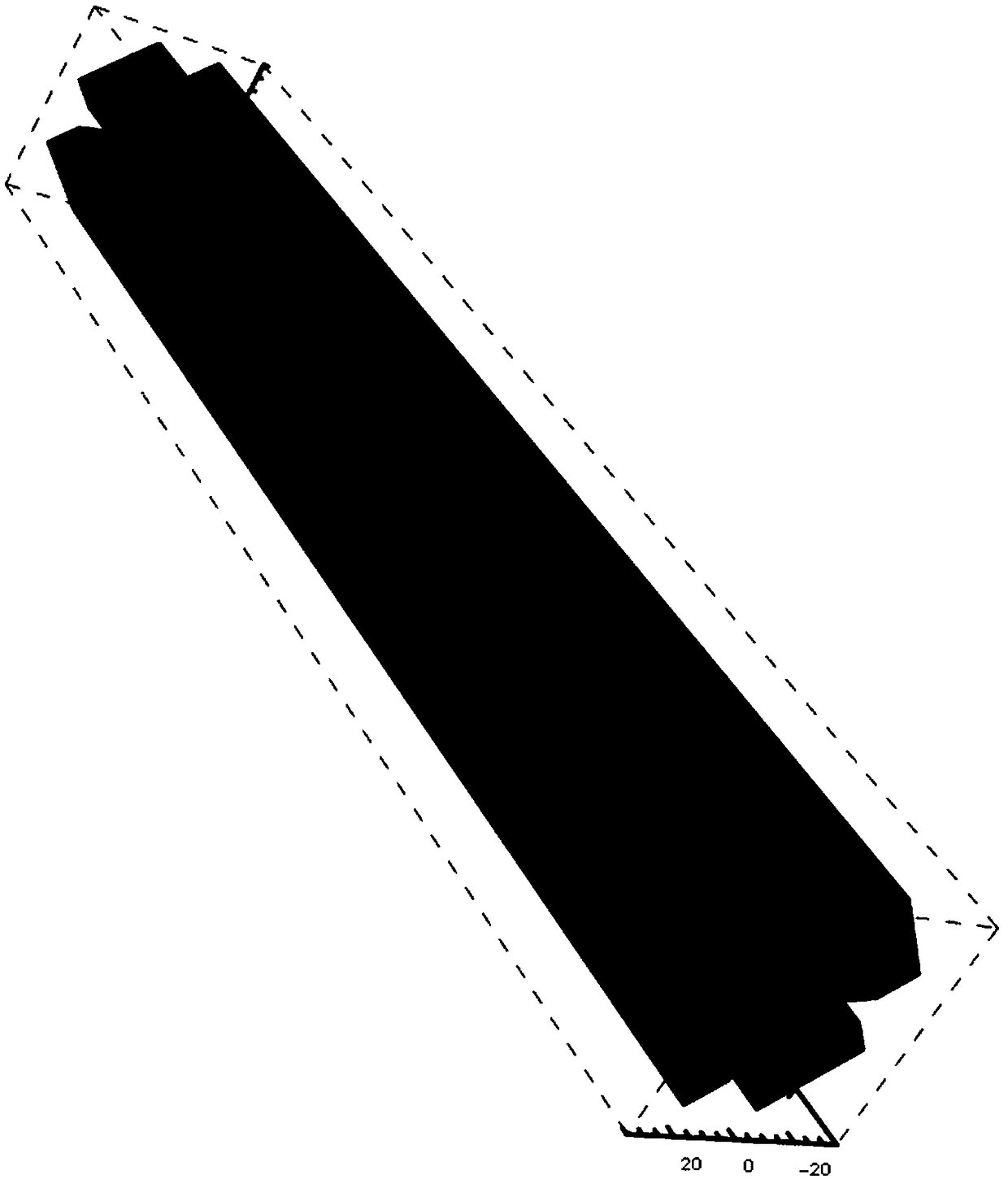
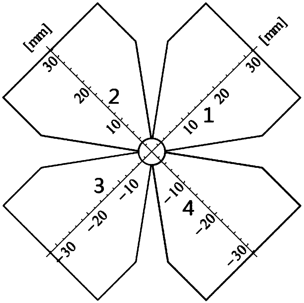
[0064] In a specific embodiment of the present invention, a polarization-tunable permanent magnet oscillator is disclosed, the schematic diagram is as follows figure 1 As shown, the undulator includes: M permanent magnet periodic units arranged in sequence along the direction of the electron beam axis, and each permanent magnet periodic unit includes four rows of permanent magnet structures; wherein, M is a natural number greater than or equal to 1; the The four rows of permanent magnet structures are evenly distributed centered on the beam aperture, and are set at an inclination of 45 degrees...


PUM

PropertyMeasurementUnit
lengthaaaaaaaaaa
widthaaaaaaaaaa
angleaaaaaaaaaa

Abstract

The invention relates to a permanent magnet undulator with adjustable polarization, which belongs to the technical field of synchrotron radiation and conquers the defects caused by vacuum outer binarysymmetry inherent in APPLE-II structure. The undulator comprises M permanent magnet periodic units arranged sequentially along the electron beam axis direction, wherein each permanent magnet periodicunit comprises four rows of permanent magnet structures; M is a natural number greater than or equal to 1; the four rows of permanent magnet structures are uniformly distributed around the beam aperture and inclined at 45 degrees. The permanent magnet undulator in the invention fundamentally conquers the inherent defects of the APPLE-II undulator, ensures that the magnetic field components in thetwo orthogonal directions can achieve the optimal performance of the design. At the same time, it solves the problem of excessive axial radiation power of DELTA undulator in horizontal and vertical linear polarization mode.

Description

technical field [0001] The invention relates to the technical field of synchrotron radiation, in particular to a permanent magnet oscillator with adjustable polarization. Background technique [0002] The full name of synchrotron radiation is synchrotron radiation, which is a high-intensity, highly collimated beam emitted along the tangential direction of electron motion when high-energy electrons are deflected in a magnetic field. In order to produce synchrotron radiation with higher intensity, current synchrotron radiation facilities use a large number of undulators. The undulator generates a periodically changing magnetic field, and the high-energy electron beam moves periodically in the undulator, and the generated light has higher intensity due to the longitudinal interference effect. [0003] Shanghai Light Source has designed the APPLE-Knot type undulator for its polarized soft X-ray users, which forms a knot structure by adding four additional magnetic arrays outsid...

Claims


Application Information

Patent Timeline
Patent Type & Authority Applications(China)
IPC IPC(8): G21K1/093H01F7/02
CPCG21K1/093H01F7/0284
Inventor 李啸宇陆辉华孙舒晨杨宇峰陈宛孙亚军李志强赵述涛张磊张祥镇龚玲玲巩克云
Owner INST OF HIGH ENERGY PHYSICS CHINESE ACAD OF SCI
Why Eureka
Try Eureka