Cavity high-Q three-mode dielectric resonance structure and filter comprising resonant structure

A medium resonance and filter technology, applied in resonators, waveguide devices, circuits, etc., can solve problems such as bulky filters

Active Publication Date: 2019-03-01
HONGKONG FINGU DEV CO LTD
View PDF6 Cites 6 Cited by
  • Summary
  • Abstract
  • Description
  • Claims
  • Application Information

AI Technical Summary

Problems solved by technology

Therefore, when the ratio of the unilateral size of the resonant cavity to the unilateral size of the dielectric resonant block is greater than 1.6, the Q value is proportional to the distance between the resonant cavity and the dielectric resonant block, but the disadvantage it brings is that the filter device is too bulky

Method used


Image

  • Cavity high-Q three-mode dielectric resonance structure and filter comprising resonant structure
  • Cavity high-Q three-mode dielectric resonance structure and filter comprising resonant structure
  • Cavity high-Q three-mode dielectric resonance structure and filter comprising resonant structure

Examples


Embodiment example 1

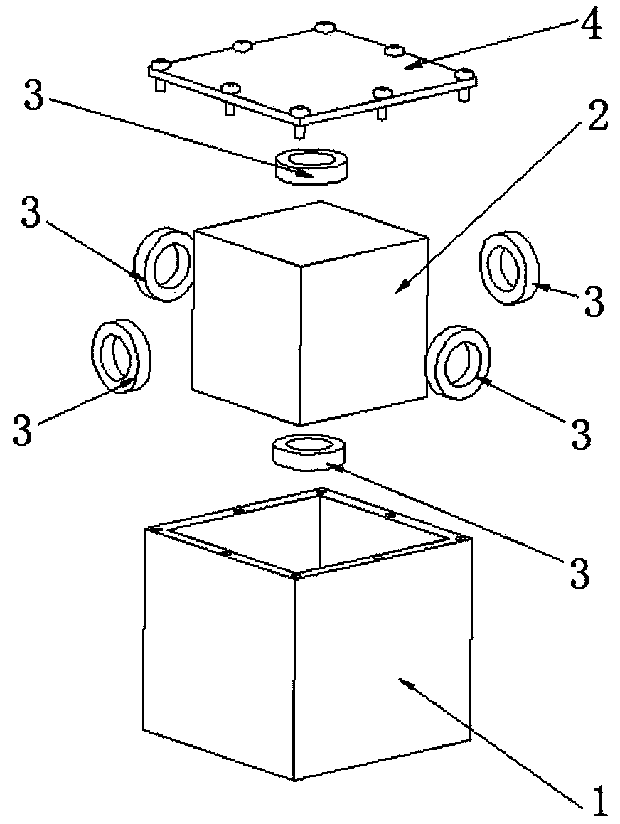
[0065] Such as figure 1 As shown, a cavity high-Q multi-mode dielectric resonant structure includes a cavity 1 and a cover plate 2. The cavity 1 is provided with a dielectric resonator block and 6 dielectric support frames, and the dielectric support frame is a cylinder shape.

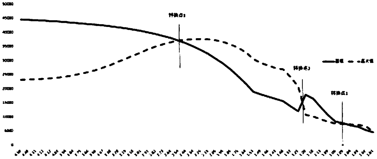
[0066] In order to clarify the essence of the present invention more clearly, the following data are further explained: the following table data is controlled within the range of 1880MHz±5MHz by the fundamental mode frequency in the multimode resonant structure, the medium adopts Er35, and the Q×F=80000 of the material is changed. The side length of the single cavity, in order to ensure the resonance frequency of the fundamental mode, the size of the dielectric resonator block changes accordingly, and the Q value of the single cavity varies with A1 / A2. Please refer to the following table for specific data. The Q value of the basic mode and the higher-order mode adjacent to the basic mode varies with A...

Embodiment Embodiment 2

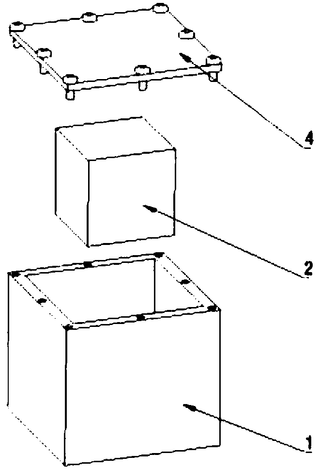
[0079] Such as image 3 As shown, a cavity high-Q multi-mode dielectric resonant structure includes a cavity 1 and a cover plate 2, and a dielectric resonator block is arranged in the cavity 1 . When the length, width and height of the inner wall of a typical single-cavity cavity are 33mm×33m×33mm, the size of the dielectric resonance block is 27.43mm×27.43mm×27.43mm (without a dielectric support frame, which is equivalent to the dielectric support frame being air), and the dielectric resonance block When the dielectric constant of the block is 35, three modes are formed when the Q×F=80000 of the material, the frequency is 1881MHz, and the Q value reaches 17746.8. The specific simulation results are as follows Figure 4 shown.

[0080]

Embodiment Embodiment 3

[0082] Such as Figure 5 As shown, a cavity high-Q multi-mode dielectric resonant structure includes a cavity 1 and a cover plate 2. The cavity 1 is provided with a dielectric resonator block and a plurality of coplanar dielectric support frames. The dielectric support The frame is cylindrical (or cuboid). When the length, width and height of the inner wall of a typical single-cavity cavity are 33mm×33m×33mm, the size of the dielectric resonator block is 27.43mm×27.43mm×27.43mm (with a dielectric support frame, and the diameter of the dielectric support frame is 2mm, and the dielectric constant is When the loss tangent is 1.06, the loss tangent is 0.0015), the dielectric constant of the dielectric resonator block is 35, and the material Q×F=80000, a three-mode is formed, the frequency is 1881MHz, and the Q value reaches 17645. The specific simulation results are as Figure 6 shown.

[0083]


PUM


Abstract

The invention discloses a cavity high-Q three-mode dielectric resonance structure and a filter comprising the resonant structure. The dielectric resonance structure comprises a cavity and a cover plate, wherein a dielectric resonance block similar to a square shape and a dielectric support frame are arranged in the cavity; the dielectric resonance block similar to a square shape and the dielectricsupport frame are arranged in the cavity form a three-mode dielectric resonance rod; air is formed between the three-mode dielectric resonance rod and the inner wall of the cavity; one end or any oneend of the dielectric resonance block similar to a square shape is connected with the dielectric support frame separately; the dielectric support frame is connected with the inner wall of the cavity;and the dielectric resonance block similar to a square shape forms three-mode resonance in three directions of X, Y and Z axis in the cavity. Compared with the existing cavity filter, the size of thecavity filter of the invention is reduced by 40%, the insertion loss is reduced by 30% or above, and it is ensured that a high Q value can be obtained under a relatively small spacing between the resonance rod and the cavity.

Description

technical field [0001] The invention relates to base station filters, antenna feeder filters, combiners and anti-interference filters used in the field of wireless communication. The types of filters can be band-pass, band-stop, high-pass and low-pass. A high-Q three-mode dielectric resonant structure and a filter containing the high-Q three-mode dielectric resonant structure. Background technique [0002] With the rapid development of the fourth-generation mobile communication to the fifth-generation mobile communication, the requirements for miniaturization and high performance of communication equipment are getting higher and higher. Traditional filters are gradually replaced by single-mode dielectric filters due to their large metal cavity and general performance. Single-mode dielectric filters mainly include TE01-mode dielectric filters and TM-mode dielectric filters, TE01-mode dielectric filters and TM-mode dielectric filters. Mode dielectric filters generally use sin...

Claims


Application Information

Patent Timeline
Patent Type & Authority Applications(China)
IPC IPC(8): H01P1/207H01P1/16
CPCH01P1/16H01P1/207H01P7/06H01P1/2086H01P7/105
Inventor 孟庆南朱晖许建军
Owner HONGKONG FINGU DEV CO LTD
Why Eureka
Try Eureka