Supercharge Your Innovation With Domain-Expert AI Agents!

System information transmission method and device

A system information and transmission method technology, applied in the field of system information transmission

Active Publication Date: 2019-03-01
HUAWEI TECH CO LTD
View PDF3 Cites 1 Cited by
  • Summary
  • Abstract
  • Description
  • Claims
  • Application Information

AI Technical Summary

Problems solved by technology

[0005] However, there is currently no corresponding solution to solve the method of transmitting system information under the architecture where CU and DU are separated.

Method used


Image

  • System information transmission method and device
  • System information transmission method and device
  • System information transmission method and device

Examples


Embodiment Construction

[0098] The technical solution in this application will be described below with reference to the accompanying drawings.

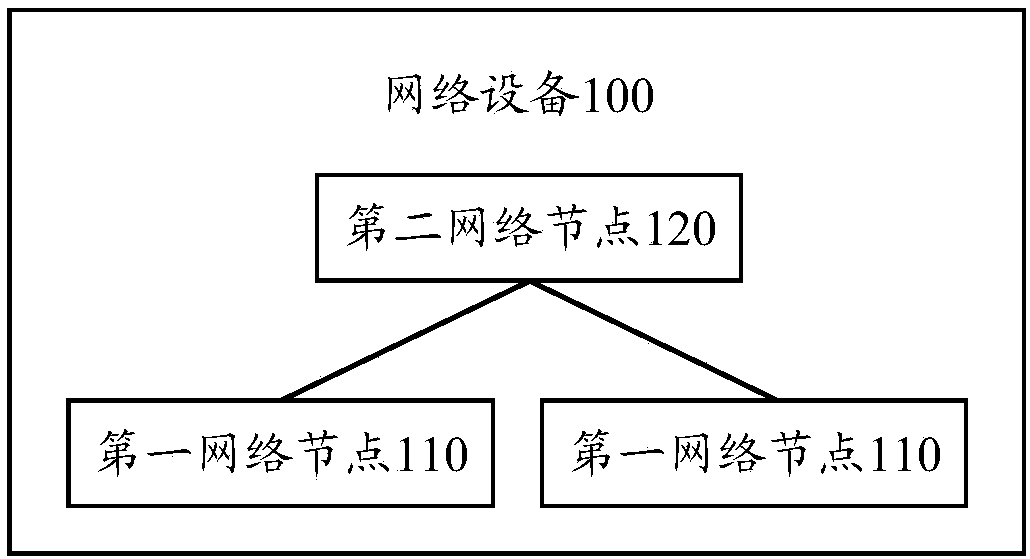
[0099] figure 1 A schematic diagram showing the application scenario of the technical solution provided by the embodiment of the present application, such as figure 1 As shown, the network device 100 can be divided into at least one first network node 110 and a second network node 120 according to protocol layer functions.

[0100] Optionally, multiple first network nodes share one second network node, which can save costs and facilitate network expansion.

[0101] Optionally, the first network node 110 may be a DU in a CU-DU separated cloud radio access network (cloud radioaccess network, CRAN) architecture, and the second network node 120 may be a CU in this architecture. There is no limit to this.

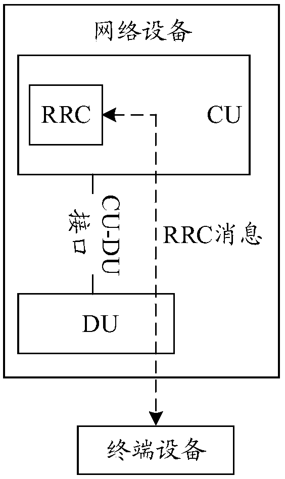
[0102] Optionally, different protocol layers may be deployed in the first network node 110 and the second network node 120, and a possible implementation m...


PUM


Abstract

The application provides a system information transmission method and device. The method includes the following steps that: a first network node receives at least one type of system information (SI) from a second network node, wherein the at least one type of SI includes the first SI; the first network node receives a request message from terminal equipment, wherein the request message is used torequest the first SI; and the first network node sends the first SI to the terminal equipment according to the request message and the at least one type of SI. The system information transmission method and device provided by the embodiment of the application can transmit the system information under the architecture that centralized units and distributed units are separated.

Description

technical field [0001] The present application relates to the field of communications, and more specifically, to a method and device for transmitting system information in the field of communications. Background technique [0002] In a communication system, a base station can be composed of a centralized unit (CU) and a distributed unit (DU), that is, the functions of the base station are split, and part of the functions of the base station are deployed in one CU, and the remaining Functions are deployed on multiple DUs, and multiple DUs share one CU, which can save costs and facilitate network expansion. [0003] The CU and DU can be divided according to the functions of the protocol layer of the protocol stack. One possible way is to combine the functions of the radio resource control (radio resource control, RRC) layer and the packet data convergence protocol (packet data convergence protocol, PDCP) layer It is deployed in the CU, and other functions of the radio link co...

Claims


Application Information

Patent Timeline
IPC IPC(8): H04W72/04H04W72/12
CPCH04W72/20H04W88/085H04W48/12H04W48/14
Inventor 权威王燕李秉肇张戬
Owner HUAWEI TECH CO LTD
Features
  • R&D
  • Intellectual Property
  • Life Sciences
  • Materials
  • Tech Scout
  • Unparalleled Data Quality
  • Higher Quality Content
  • 60% Fewer Hallucinations
Learn More