
Juicer having improved juicing performance

A juicer and performance technology, applied in the field of juicer, can solve the problems of reduced juicer efficiency, pressurization of juicers, etc., and achieve the effect of improving juicer performance

Inactive Publication Date: 2019-03-01
李文铉
View PDF6 Cites 2 Cited by
  • Summary
  • Abstract
  • Description
  • Claims
  • Application Information

AI Technical Summary

Problems solved by technology

[0016] In the existing juice extractor, there is a problem that the squeezed material is not sufficiently pressurized between the casing and the juice extracting roller, so that the juice extracting efficiency is reduced.

Method used


Image

  • Juicer having improved juicing performance
  • Juicer having improved juicing performance
  • Juicer having improved juicing performance

Examples


Embodiment Construction

[0051] Hereinafter, a juicer with improved juice extraction performance will be described in detail with reference to the drawings.

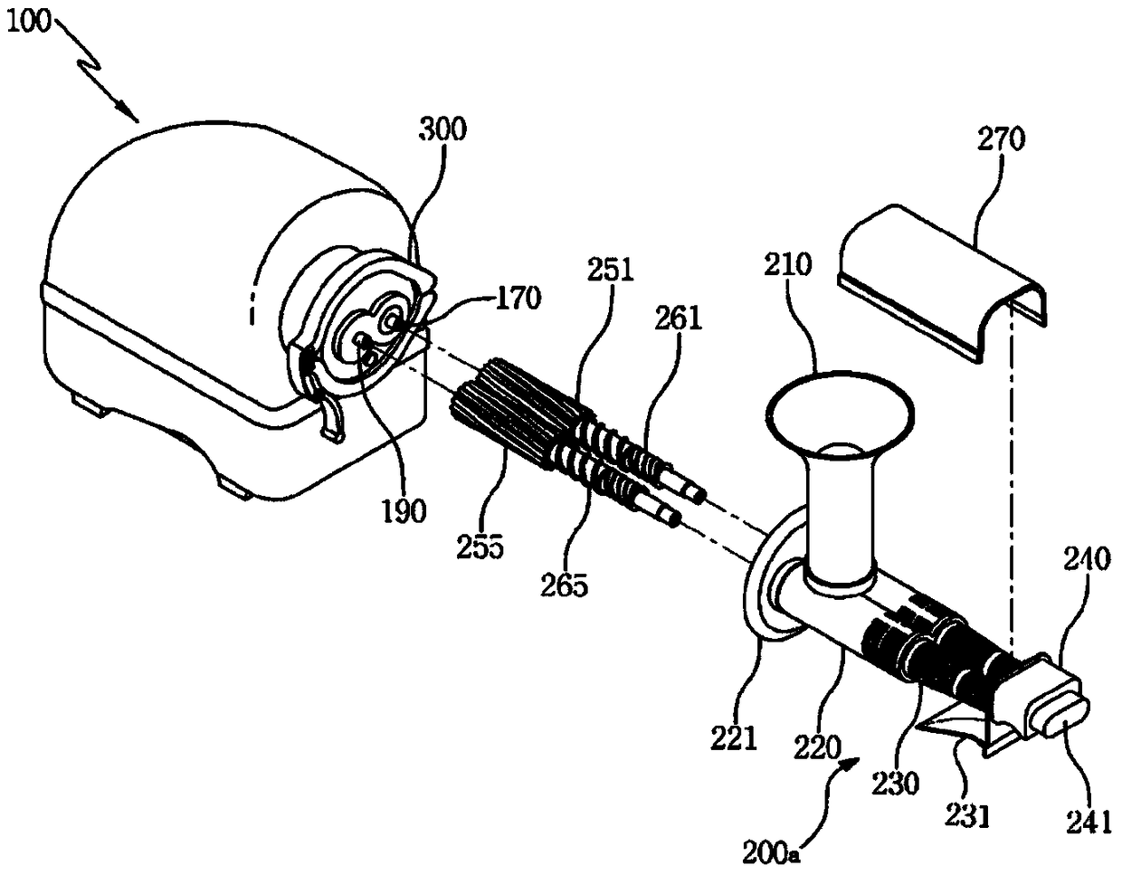
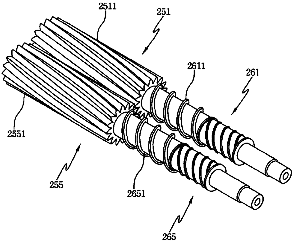
[0052] image 3 is icon figure 2 The perspective view of the pulverizing roller part and the juicing roller part of the Figure 4 is a sectional view schematically illustrating a drive screw of a juice extractor according to the present invention, Figure 5 is icon Figure 4 A sectional view of the section of the A-A section, Figure 6 is an enlarged icon Figure 4 A cross-sectional view of Part B, Figure 7 is icon Figure 4 A sectional view of the section of the C-C part, Figure 8 is a perspective view illustrating a contact electrode of a juice extractor according to the present invention, Figure 9 is a sectional view illustrating a modified example of the juice extractor according to the present invention.

[0053] exist Figure 4 In , the horizontal direction is referred to as "longitudinal direction", the longitudinal directio...


PUM


Abstract

The present invention relates to a juicer having an improved juicing performance. The juice is characterized by comprising: a housing having a motor embedded therein; a driving shaft exposed through one side of the housing and driven to rotate by the motor; a driving screw which is coupled to the driving shaft and rotates integrally with the driving shaft, and which is contained in a screw housing; and a screw housing which is coupled to the housing in an attachable / detachable manner, and which is a hollow body having a hopper, wherein the driving screw comprises a driving screw body having aninstallation groove formed thereon so as to be open toward the housing, at least one piezoelectric element provided in the installation groove of the driving screw body, and a contact terminal whichis electrically connected to the piezoelectric element, and which electrically contacts a contact electrode provided on the housing; and the housing has a contact electrode.

Description

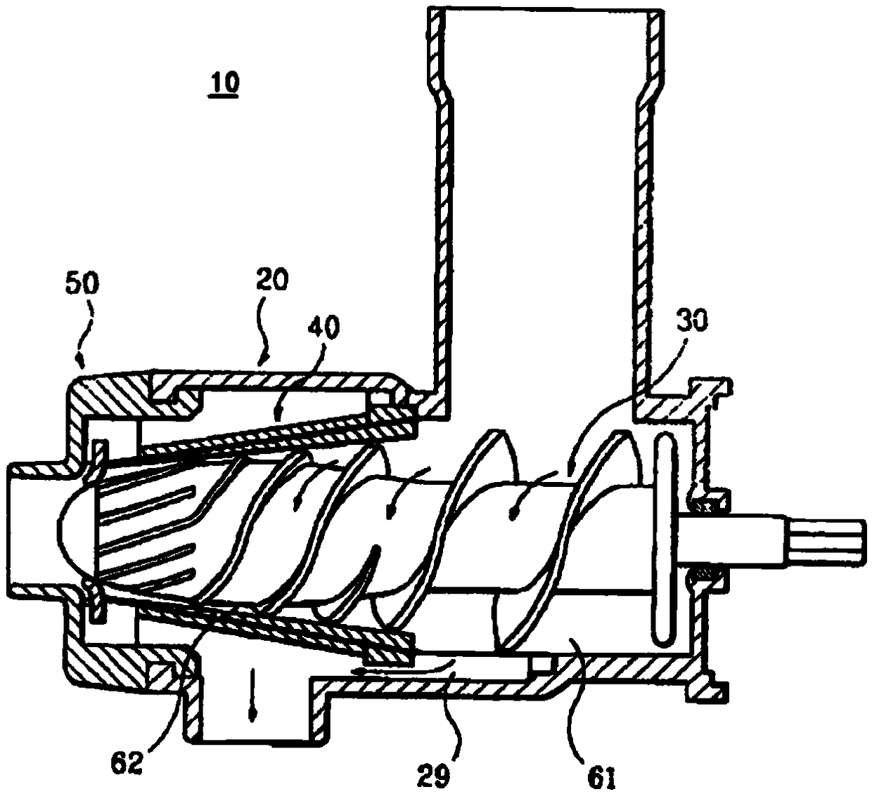
technical field [0001] The present invention relates to a juice extractor with improved juice extracting performance, in particular to a juice extractor equipped with a piezoelectric element, and through the piezoelectric effect of the piezoelectric element, the juice extractor is fully pressurized between the screw housing and the driving screw. A juice extractor with improved juice extraction performance. Background technique [0002] like figure 1 As shown, the existing juice extractor 10 includes a main body (not shown) which is a hollow body equipped with a motor, a housing 20, a juice extraction roller part 30, a juice extraction barrel 40, a discharge path 29 and a housing cap 50 . [0003] The casing 20 is divided into: a fold-in part 61 installed on one side of the main body to allow the squeezed juice to flow into the inside; and a crushing part 62 to crush / squeeze the juiced material. [0004] The juice extraction roller part 30 is installed inside the housing ...

Claims


Application Information

Patent Timeline
IPC IPC(8): A47J19/02H01L41/09B30B9/16
CPCA47J19/025B30B9/16H10N30/20
Inventor 李文铉
Owner 李文铉
Learn More